xii
Table of Figures
Figure 1: APP-601 Computer Control Chassis Front View (Fanless) ......................................................... 3-3
Figure 2: APP-501 Computer Control Chassis Front View......................................................................... 3-3
Figure 3: Data Chassis Front View .............................................................................................................. 3-3
Figure 4: Chassis Interconnection Diagram (Reference) (with APP-501 Computer Control Chassis) ..... 3-12
Figure 5: Chassis Interconnection Diagram (Reference) (with APP-601 Computer Control Chassis) ..... 3-13
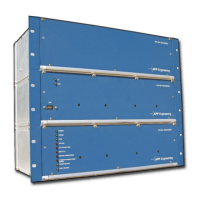
Figure 6: APP-601 Computer Control Chassis Front View......................................................................... 4-6
Figure 7: APP-601 Computer Control Chassis Rear View .......................................................................... 4-6
Figure 8: APP-501 Computer Control Chassis 3D View ............................................................................ 4-8
Figure 9: APP-501 Computer Control Chassis Front View......................................................................... 4-9
Figure 10: APP-501 Computer Control Chassis Rear view......................................................................... 4-9
Figure 11: Cross Trigger over IP Network ................................................................................................ 4-14
Figure 12: Cross Trigger Wiring, 3 DFR Example ................................................................................... 4-15
Figure 13: APP-601 Data Chassis 3D View .............................................................................................. 4-19
Figure 14: APP-601 Data Chassis Front View .......................................................................................... 4-20
Figure 15: APP-601 Data Chassis Rear View ........................................................................................... 4-20
Figure 16: Recorder Configuration Window ............................................................................................... 5-3
Figure 17: Point Assignment Window’s Chassis Configuration ................................................................. 5-4
Figure 18: Point Assignment Window: General Settings Tab ..................................................................... 5-5
Figure 19: Windows Logon & Setup Window ............................................................................................ 5-6
Figure 20: APP Recorder Program Main Window ...................................................................................... 6-3
Figure 21: Analog Tab ................................................................................................................................. 6-3
Figure 22: Triggers Tab ............................................................................................................................... 6-4
Figure 23: Events/SER Tab ......................................................................................................................... 6-4
Figure 24: SER Report Tab ......................................................................................................................... 6-4
Figure 25: Fault Location Tab ..................................................................................................................... 6-5
Figure 26: Example of APP 601 Recorder Configuration Window—Main Tab ......................................... 6-9
Figure 27: Recorder Configuration Window —Automatic Tasks Tab ...................................................... 6-13
Figure 28: Printing Format Window ......................................................................................................... 6-17
Figure 29: Default Report Format ............................................................................................................. 6-19
Figure 30: Report with Spread digital among graphs checked .................................................................. 6-19
Figure 31: Auto Email Setup Window ...................................................................................................... 6-21
Figure 32: Manual Emailing Window ....................................................................................................... 6-22