Using the OScope 8-6
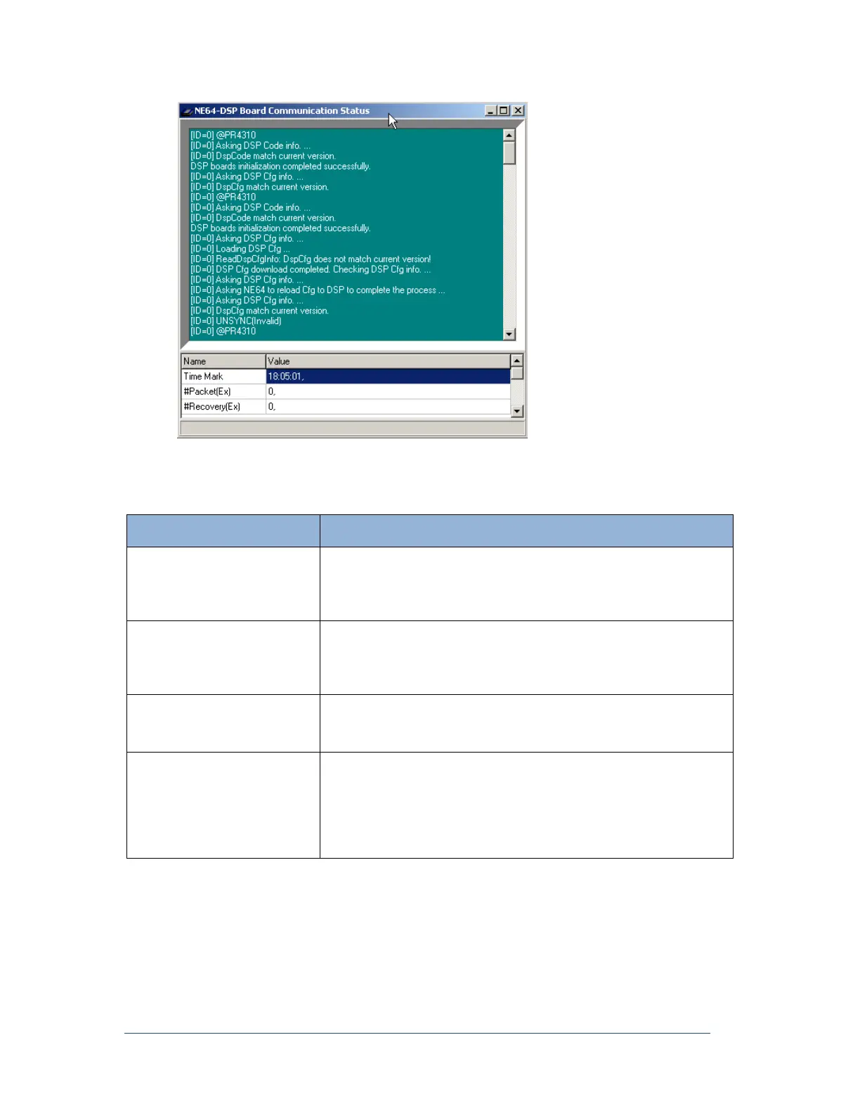
Figure 61: DSP Board Communication Status Window
The following table describes the fields that appear in this window.
Table 16: DSP Board Communication Status Window—Fields
The absolute times of the 1PPS signal for all the DSP boards, are
displayed here. The times are updated every 30 seconds. If multiple
times are displayed, meaning that there are two or more DSP boards,
they should be the same.
If the extended recording feature is enabled in the Point Assignment
Record (General Settings tab: Sampling tab), packet transfers or data
flow, from the DSP circuit boards to the computer hard drive, can be
seen here.
If the extended recording feature is enabled, this area will keep a
running total of the number of times packets have had to be re-sent
from the DSP board to the computer hard drive.
The temperatures of the DSP boards are displayed here. In a normal
situation, the display may look something like (0, 45C). The zero
indicates that the DSP temperature is below 65C and it is now 45C. If
the temperature on the board is over 65C, the zero will become one.
Because the indicator (0 or 1) is sensed differently than the reading,
you can trust that the temperature reading is correct.