Hardware 4-23
4.7 Networking
The Computer Control Chassis uses two separate network setups. One is for recorder functionality (chassis-
to-chassis communication & data transfer) and the second is for communication between the recorder (APP
Recorder Software) and the master station (APP ClearView Software).
The first network connection will be called “Local Area Connection (To DSP)” or similar. If a complete
system was purchased, the TCP/IP settings will have already been setup at the factory.
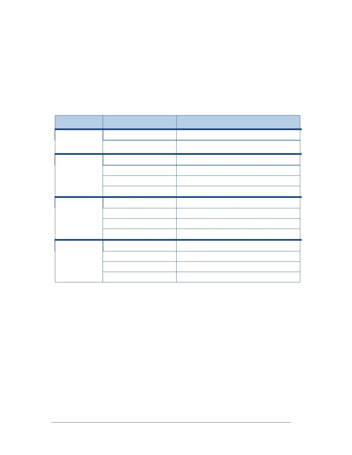
The following table lists the standard Ethernet and IP addresses for the DSP network.
Table 8: Ethernet and IP Addresses for the DSP Network
Computer
Control Chassis
(Typical)
1
st
Data Chassis
(Typical)
2nd Data Chassis
(Typical)
3rd Data Chassis
(Typical)
Note: The pattern continues for additional Data chassis.
The second connection will be called “Local Area Connection (To LAN)” or similar. Under TCP/IP
properties the user can enter their static IP Address, Subnet Mask, and Default Gateway to enable the
recorder to communicate with the master station program over the corporate LAN/WAN.