Using the APP Recorder 6-53
In this case, start the APP ClearView program, connect the programming cable between
your laptop (COM 1) and the DSP board, click on Tools, and then click on DSP Board’s
Ethernet Settings. A physical connection should be established and you will be able to
make the necessary settings changes. If a connection is not established, verify that your
laptop and the setting on the DSP Board’s Ethernet Settings are set to the same Com
Port (usually COM 1).
3. Verify that the Data chassis is powered on.
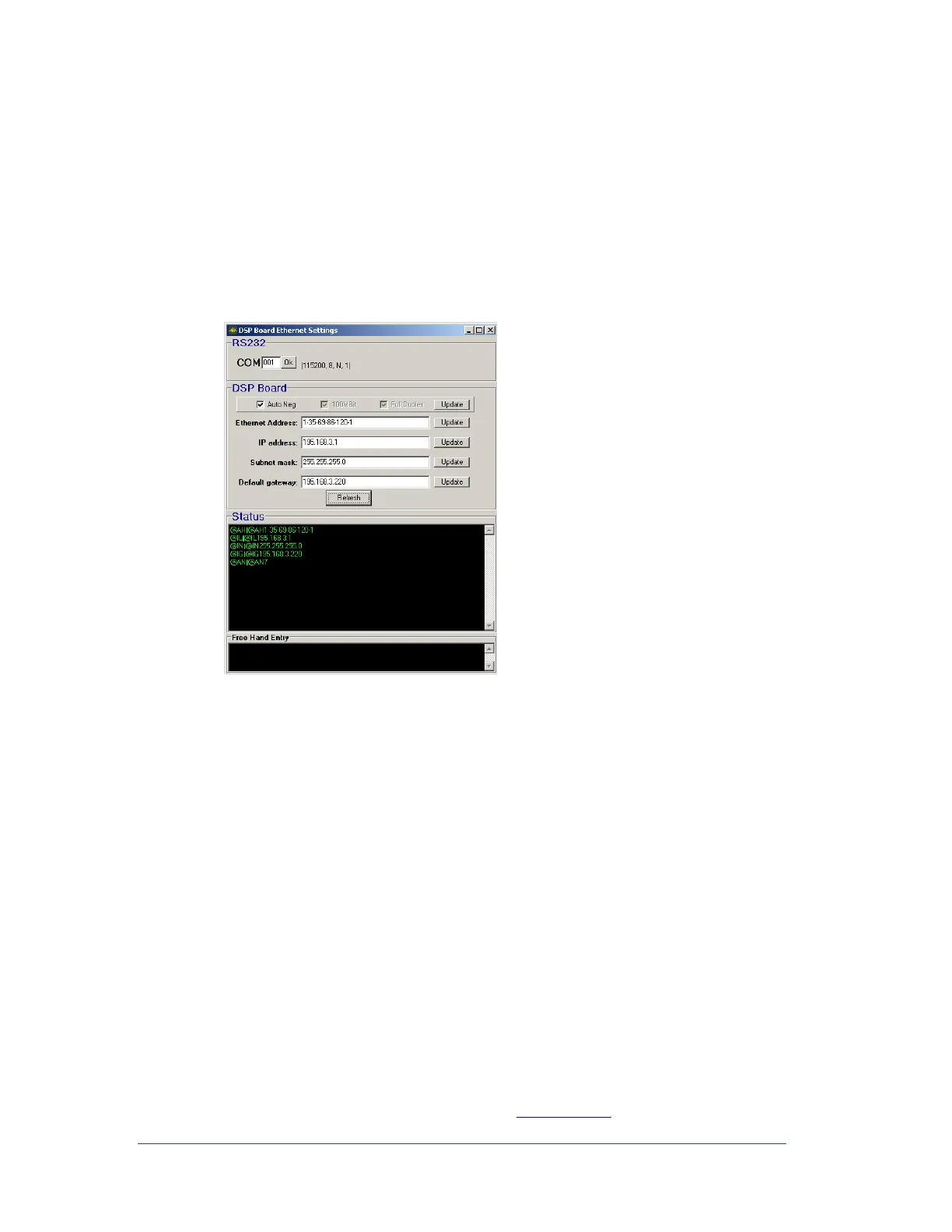
4. In the APP Recorder window, from the Tools menu, click DSP Board’s Ethernet Settings.
The following window appears.
Figure 54: DSP Board Setup Window
5. DSP Board check boxes; Auto Negotiate (Auto Neg), 100 Mbit, and Full Duplex. These are to
configure physical connectivity parameters to the APP Recorder or to a communications device
(switch). Auto Neg is the default setting and is used when connected directly to the APP Recorder
computer or to an APP Engineering supplied switch. Customer specified programmable switches
not set to Auto Negotiate may need to check the 100Mbit and Full Duplex options to successfully
communicate with the switch.
6. Make the necessary updates to the address fields. See Examples of Ethernet and IP Addresses on
page 6-52 for more information.
7. Click Update.
If you change an IP Address, be sure to enter the new DSP IP Address
in the Point Assignment Record. See Figure 17: Point Assignment
Window’s Chassis Configuration
6.14 Configuring a Phasor Measurement Unit (PMU)
The APP-601 Recorder PMU feature supports the IEEE Standard C37.118-2005 which describes the
functional requirements for PMUs and basic data measurement and verification requirements. For
additional information on the benefits of using PMUs, go to www.naspi.org