25[Meas] Key
and BUS (RS-232).
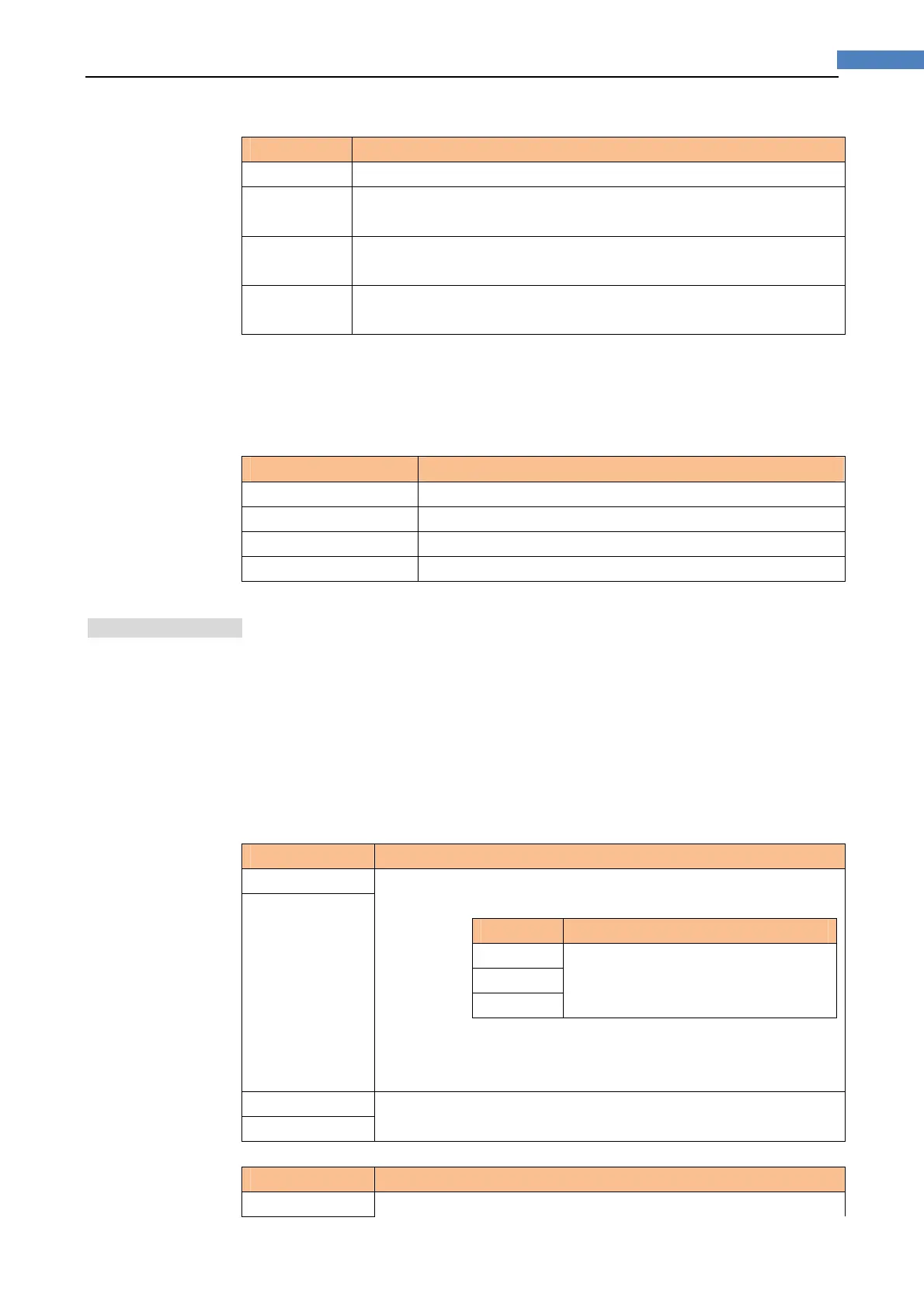
Trigger Mode Description
INT AT281x continuously repeats the measurement cycle.
MAN AT281x performs one cycle of measurement each time you press the
[Trig] key.
EXT AT281x performs one cycle of measurement each time a rising pulse is
input to the handler external trigger input pin on the rear panel.
BUS AT281x performs one cycle of measurement each time it receives a
trigger command sent via RS-232.
Procedure for choosing trigger mode [TRIG]
Step 1. Press the [Meas] key
Step 2. Use the cursor key to select [TRIG] field
Step 3. Use the soft keys to select desired trigger mode.
Soft key Function
INT Internal Trigger Mode
MAN Manual Trigger Mode
EXT External Trigger Mode
BUS BUS Trigger Mode
4.1.5 TestSignalVoltageLevel[LEVEL]
The AT281x’s test signal voltage level can be set as the effective value (RMS value) of
a sine wave
of the test frequency from the unit’s internal oscillator.
The output impedance can be set to 30, 50 or 100.
Test signal level setting procedure
Step 1. Press the [Meas] key
Step 2. Use the cursor key to select [LEVEL] field
Step 3. Use the soft keys or numeric entry keys to enter the test signal voltage level.
AT2816X, AT2818:
Soft key Function
INCR ++ Refer to
AT2817:
Soft key Function
0.1V
0.3V
1.0V
Table 4-15Table 4-8 AT2818’s Test Frequency that can be set
using INCR++/DECR--
(*Note: These two items are not available in AT2817)
DECR --
INCR + Refer to Table 4-16
(*Note: These two items are not available in AT2817)
DECR -
AT2817:
Soft key Function
0.1V