51Handler Interface
8. HandlerInterface
This chapter provides information of AT281x’s built-in handler interface. Include:
Pin Assignment
Circuit Diagram
Timing Chart
The AT281x’s built-in handler interface outputs signals that indicate the end of a
measurement cycle, the result of bin sorting by the comparator. In addition, the
instrument accepts input of external trigger. You can use these signals to easily integrate
the AT281x with a component handler or system controller. This means that you can
fully automate such tasks as component inspection, component sorting, and processing
of quality management data for higher manufacturing efficiency.
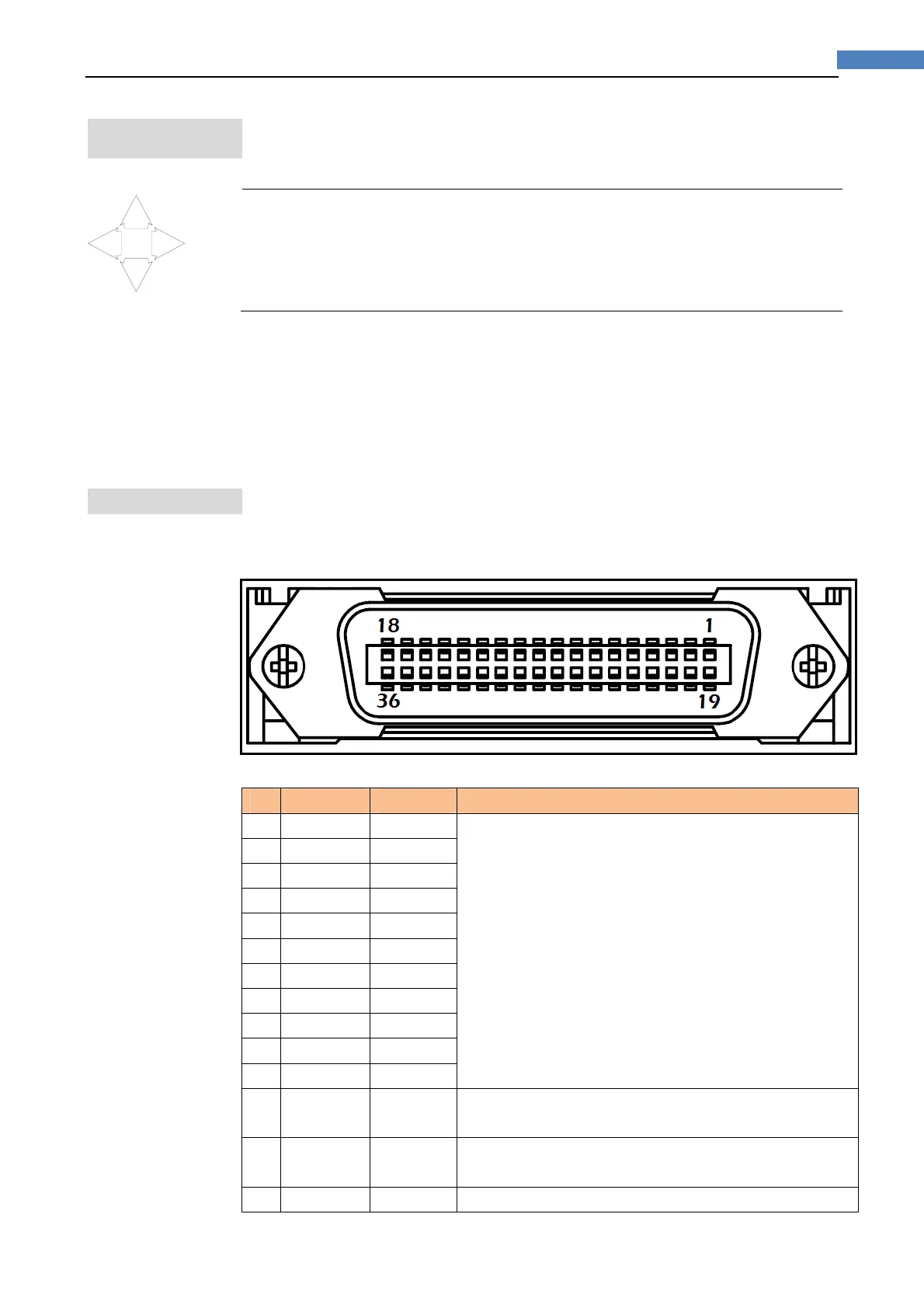
8.1 PinAssignment
Figure8‐1 PinAssignment
Table8‐1 DescriptionofHandlerInterfaceSignals
Pin Signal Direction Overview
1 /BIN1 Output The result of sorting.
Open-collector based.
If EX-V2 signal was connected with EX-VCC, a built-in
5k pull-up resistance used.
2 /BIN2 Output
3 /BIN3 Output
4 /BIN4 Output
5 /BIN5 Output
6 /BIN6 Output
7 /BIN7 Output
8 /BIN8 Output
9 /BIN9 Output
10 /OUT Output
11 /AUX Output
12 Trig-8V Input
An external trigger signal for 8V EX-VCC.
Connect to this pin when EX-VCC = 5~8V.
13 Trig-24V Input
An external trigger signal for 24V EX-VCC.
Connect to this pin when EX-VCC=8~24V
14 EX-V2 Power External DC Voltage.