53Handler Interface
8.3 ElectricalCharacteristics
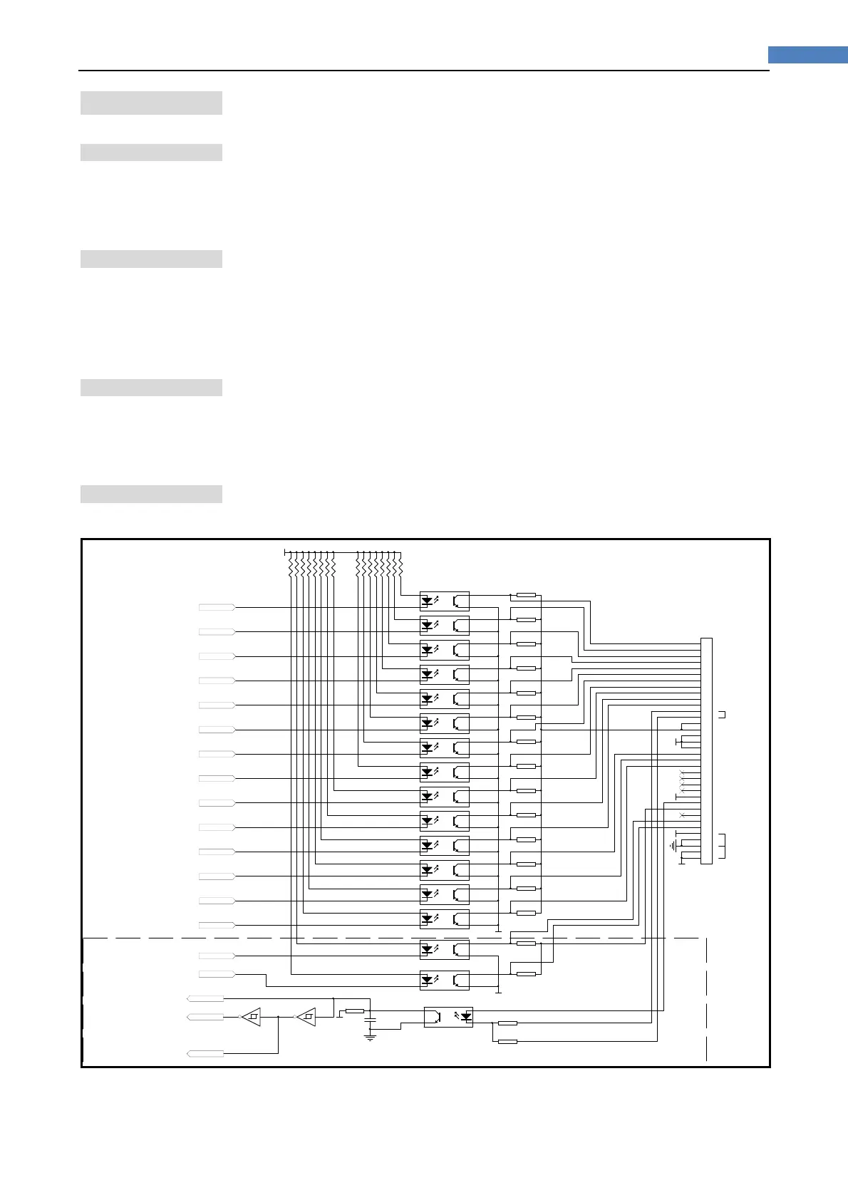
8.3.1 InputSignal:
Each input signal is connected to the LED (cathode side) of the photo-coupler. The LED
(anode side) is connected to the pull-up power supply voltage.
8.3.2 OutputSignal:
Each output signal is outputted via an open collector by using a photo-coupler. The
voltage of each output is obtained by connecting pull-up resistors, inside or outside of the
AT281x.
8.3.3 Powersupply
The power supply for the judgment output signal pull-up and that for the operation
output signal pull-up and input signal drive can be set separately. You can select from
+3.3V to +35V external power supply.
8.3.4 Schematic
Figure8‐2 Handlerschematic
1
2
3
4
5
6
7
8
9
10
11
12
13
14
15
16
17
18
19
20
21
22
23
24
25
26
27
28
29
30
31
32
33
34
35
36
CN 80 1
36PIN
1
2
4
3
P8 02
PC817
1
2
4
3
P8 01
PC817
1
2
4
3
P8 03
PC817
1
2
4
3
P8 04
PC817
1
2
4
3
P8 05
PC817
1
2
4
3
P8 16
PC817
1
2
4
3
P8 11
PC817
1
2
4
3
P8 17
PC817
R8 33
2.2k
C8 01
1n
+3. 3
R8 17
4.99k
R8 18
4.99k
R8 19
4.99k
R8 20
4.99k
R8 21
4.99k
R8 22
4.99k
R8 23
4.99k
AB I N1
AB I N2
AB I N3
AA UX
AO UT
AI D X
AE OM
COM1
COM1
COM2
COM2
TRI G8 V
BB I N1
BB I N2
BB I N3
BO UT
BA UX
BI D X
BE OM
EXT.DCV : +3 to +24V
R8 34
1.2 k
R8 35
2.2 k
TRI G8 V
TRI GGER
AB I N4
AB I N5
AB I N6
AB I N7
AB I N8
AB I N9
1
2
4
3
P8 13
PC817
1
2
4
3
P8 14
PC817
1
2
4
3
P8 15
PC817
AP H I
AP LO
AS RE J
BS REJBS REJ
BP LO
BP H I
BB I N4
BB I N5
BB I N6
BB I N7
BB I N8
BB I N9
R8 24
4.99k
R8 25
4.99k
R8 26
4.99k
R8 27
4.99k
R8 28
4.99k
R8 29
4.99k
R8 30
4.99k
R8 31
4.99k
R8 32
4.99k
LOW ASSERTED
1
2
4
3
P8 06
PC817
1
2
4
3
P8 07
PC817
1
2
4
3
P8 08
PC817
1
2
4
3
P8 09
PC817
1
2
4
3
P8 10
PC817
1
2
4
3
P8 12
PC817
Internal Power
TRI G2 4V
TRI G2 4V
TRIG 3V : SH ORT
+3. 3
+3. 3
BIN1
BIN2
BIN3
BIN4
BIN5
BIN6
BIN7
BIN8
BIN9
OU T
AUX
PHI
PLO
SREJ
TR IG _FALL
TR IG_RISE
R8
499
R8
499
R8
R8
499
+3. 3
IDX
EOM
TR IG
10 11
U801E
74HC14
8 9
U801D
74HC14
EXV1
BIT0
BIT1
BIT2
BIT3
BIT4
BIT5
BIT6
BIT7
BIT8
BIT9
BIT10
BIT11
BIT12
BIT13
BIT14
BIT15
NC
BIT0
BIT1
BIT2
BIT3
BIT4
BIT5
BIT6
PUS H VC C
PUS H
PUS H VC C
------- -------
Figure8‐3
Typical Circuit Diagram of Handler Interface Input signals.