5-22
Operation
X6 - P/N 6525032M1
Power take-off engagement [4.2.d]
1– Select the required speed with the lever (1 - Fig.5-15B);
2– Select the PTO type (normal-eco) with the lever (2)
(only valid for 4-speed setup);
3– Operate the PTO engagement button (1 - Fig.5-14).
4– Engage/disengage the PTO with the engaging control
(1 - Fig.5-14) during work.
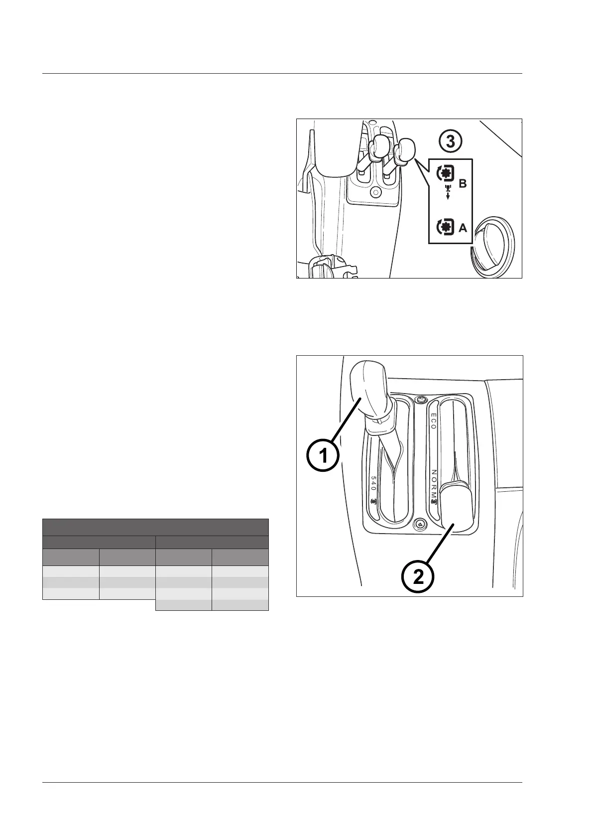
PTO type selector lever (3 - Fig.5-15A).
Interpretation of symbols on the decal beside the control
lever (Fig.5-15A).
A - Independent PTO engaged.
PTO driven directly from the engine.
IMPORTANT: Always keep the lever in position A
during work. Shift the lever to position B only if the
synchronized PTO has to be used. Return the lever to
Pos. A after using the synchronised PTO.
B - Synchronised PTO proportional to ground speed
engaged (optional).
PTO driven by the gearbox
NOTE: the PTO operation selector lever (3-Fig.5-15A)
has no neutral position. The mechanical neutral position
is obtained by bringing the speed range selector lever
(1 - Fig.5-15) in the middle position "O".
IMPORTANT: The PTO mode selector lever, independent
or synchronised (optional), controls a mechanical coupler
that ensures the maximum safety in both operation modes.
The passage from a mode to another, however, is only
possible when the teeth are aligned. The procedure is
described under the headings "Direct power take-off" and
"Synchronised power take-off" hereunder.
Independent PTO engagement
It is driven directly by the engine, and its operation is fully
independent of the tractor's ground speed.
PTO version
2 speeds 4 speeds
PTO type Engine rate PTO type Engine rate
540 1944 540 1944
540E 1377 540E 1580
1000 1917 1000 1952
1000E 1586
The direct PTO should be engaged with the engine at
idling speed and without hesitation. Do not heed any
noises due to tooth meshing.
Always keep the lever (3) in "A" position (Fig.5-15A), for
independent PTO engaged.
The synchro PTO should only be engaged when actually
required (see the section Synchronised Poser Take-Off).
Hydraulic PTO control levers [4.2.d]
Fig. 5-15A
3 - PTO operation selector lever
A - Independent power take-off
B - Synchronised power take-off
2 - PTO type selector lever (setup with 4-speed PTO)
- Normal
- Eco
Engine - Power take-off RPM meter
NOTE:For information about operation of the PTO, refer
to the description of the instrument cluster in the chapter
"Instruments and Programming".
Fig. 5-15B
 Loading...