5-58
Operation
X6 - P/N 6525032M1
Hitching an implement
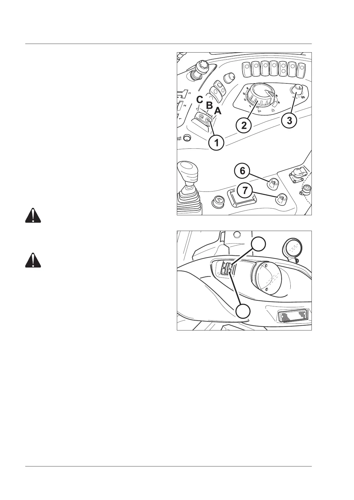
With the controls inside the cab on the right
side
- Turn the hitch control switch (1) to Pos. C to enable the
hitch control panel.
- Turn the control switch to the working position (A).
- Turn the function selector (3) anti-clockwise to select
position control mode.
- Turn the knob (2) anti-clockwise to lower the links.
The links-down indicator will light up.
- Manoeuvre the tractor to the required position and hitch
the implement's ball-ends on to the ends of the links.
Fit safety pins to secure the hitch.
Hitch up the top link.
- Turn the knob (2) clockwise to raise the implement.
The links-up indicator will light up.
External control buttons
WARNING: External controls must be operated
at a safe distance, standing on one side outside
the tractor and out of the overall width of
mudguards. It is expressly forbidden to oper-
ate the controls from the rear of the tractor or
standing on the inner side of wheels.
DANGER: Never reach with arms, legs or any
part of your body in the area near the three-
point linkage or the implement when operat-
ing the outer switch. Never let another person
operate the other control group. Walk around
the tractor or the implement to go from a
control group the other. NEVER pass between
implement and tractor.
There is no need to enable the hitch in order to use the
external control buttons.
To use the external controls, just press on the buttons to
raise or lower the lift links. Now enable the hitch control
panel by means of the switch (1).
Always operate the external switches according to the
following procedure:
– Shift the transmission to neutral. Engage the park brake.
– Press the switch (9) to raise the hitch. Press the switch
(10) to lower the hitch.
– When the switch is released, the hitch stops at the
position reached in that moment.
– If both switches are pressed together the hitch will stop.
NOTE:
With the external switches the hitch moves at a lower
speed than with the controls in the cab. Down speed
regulation remains disabled.
To enable again the hitch control panel controls, release
the safety device by setting the switch (1) to (Pos. C) and
then to working position (A).
Fig.5-34
9 - Up 10 - Down
Fig.5-33
9
10
 Loading...