2-25
Safety notes
2
P/N 6525032M1 - X6
Tractor stability
The following procedure describes the conditions for a
proper stability and gives instructions to calculate correct
front and rear ballasting. For ballasting, also consult the
pertaining recommendations in this manual. For maximum
allowed weight in running order, refer to weight and load
data in this manual.
RISK OF OVERTURNING!
To prevent machine instability, ALWAYS evalu-
ate and comply with stability requirements as
given in this manual.
Failure to comply with these directions could
cause injuries or death.
The following procedure and calculations refer to the
tractor on level ground.
RISK OF OVERTURNING!
ALWAYS keep in mind the possible conse-
quences of downhill driving and steep slopes
on tractor's stability. Such conditions can affect
operation, turning and braking performances.
Adjust ballasts and ground speed to ensure a
safe and stabile braking, as well as braking
performances required in critical conditions.
Failure to comply with these directions could
cause injuries or death.
How to calculate tractor stability as suggested by EN
12525.
Data required to evaluate tractor stability
1. The weight of the implement (seed drills, fertiliser
spreaders, etc.) and of the relative filling material must
be added to the weight data of the loaded tractor.
2. Ballasting data, either with ballast blocks or liquid
ballast, on front or rear wheels must be added to MF,
MR and MT data.
3. If two-wheel trailed implements are mounted, value
c corresponds to the distance of the rear axle centre
line and the attachment point, value d is 0 (zero) and
BR corresponds to the downward load of the trailer
on its attachment point.
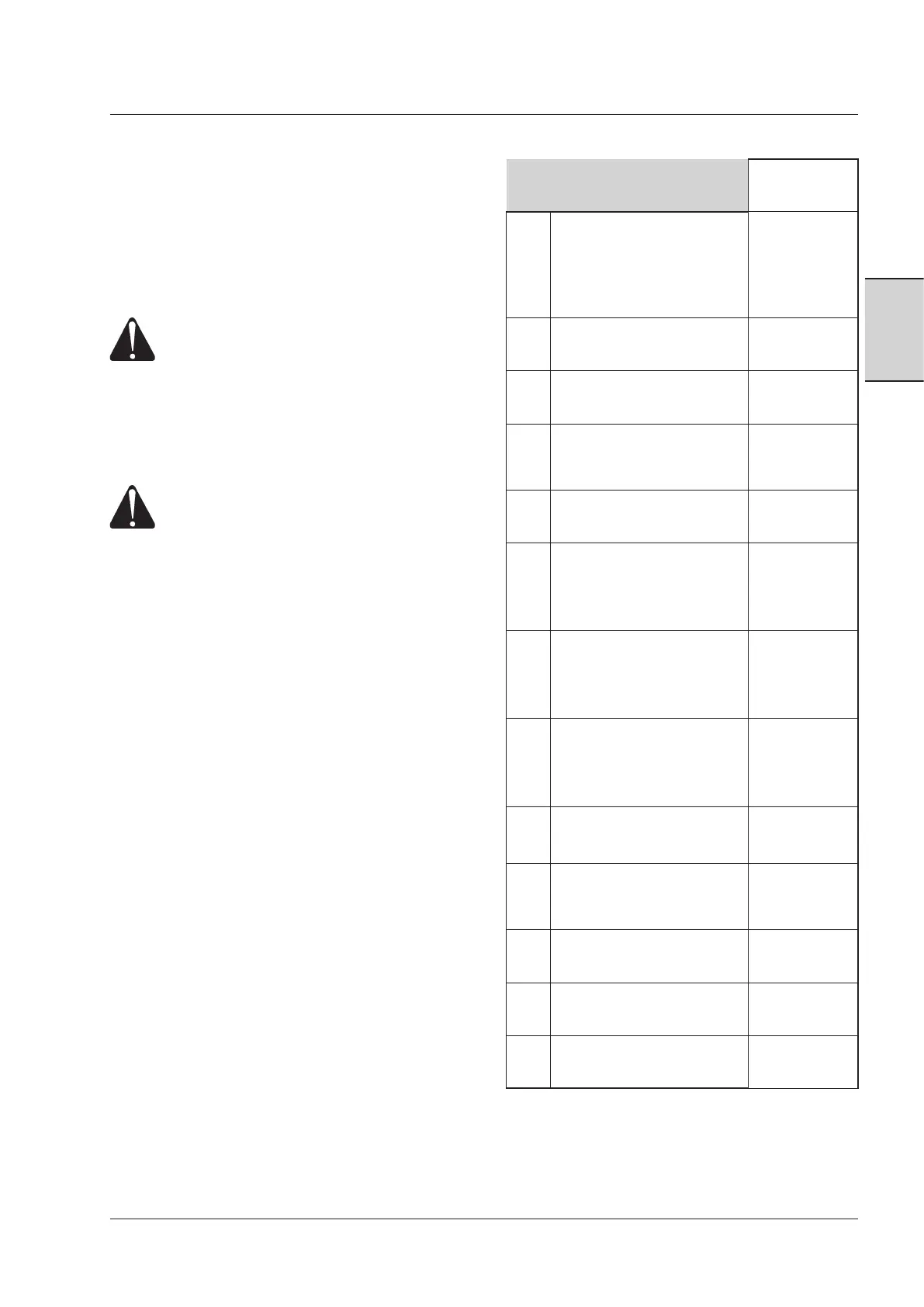
Key
Please
refer to:
MT
Tractor's empty weight = trac-
tor with standard equipment,
fuel at min. level, without liq-
uid ballast or blocks, without
operator and with single tyres
This manual
MF Empty load on front axle This manual
MR Empty load on rear axle This manual
a
Distance from front load centre
of gravity to centre line of the
front axle
I m p l e m e n t ' s
manual or to be
measured
b
Centre distance
This manual
c
Distance from rear axle centre
line to bottom attachment
point of three-point linkage
This manual or
to be measured
d
Distance from centre of grav-
ity of rear load to bottom at-
tachment point of three-point
linkage
I m p l e m e n t ' s
manual or to be
measured
e
Distance from centre line of
rear axle and centre of gravity
(COG) of MT (tractor's empty
weight)
To be calculated
(a cco rdi ng to
formula in the
following pages)
BF
Weight of front equipment or
front ballasts
I m p l e m e n t ' s
manual or to be
measured
BR
Weight of rear equipment or
rear ballasts
I m p l e m e n t ' s
manual or to be
measured
MPT
max
Max. allowed weight with
loaded tractor
This manual
MPF
max
Max. allowed weight on front
axle
This manual
MPR
max
Max. allowed weight on rear
axle
This manual