5-56
Operation
X6 - P/N 6525032M1
ELECTRONICALLY CONTROLLED HY-
DRAULIC hitch
Description
Electronic control of the hitch gives a number of major
benefits. In particular, control and response signals can
be processed and action taken to adjust for variations in
ground conditions encountered by the implement in a
fraction of the time possible with manual controls.
In order to use the rear hitch system in the best and safest
conditions, the operator must become familiar with the
controls on the right side of the cab.
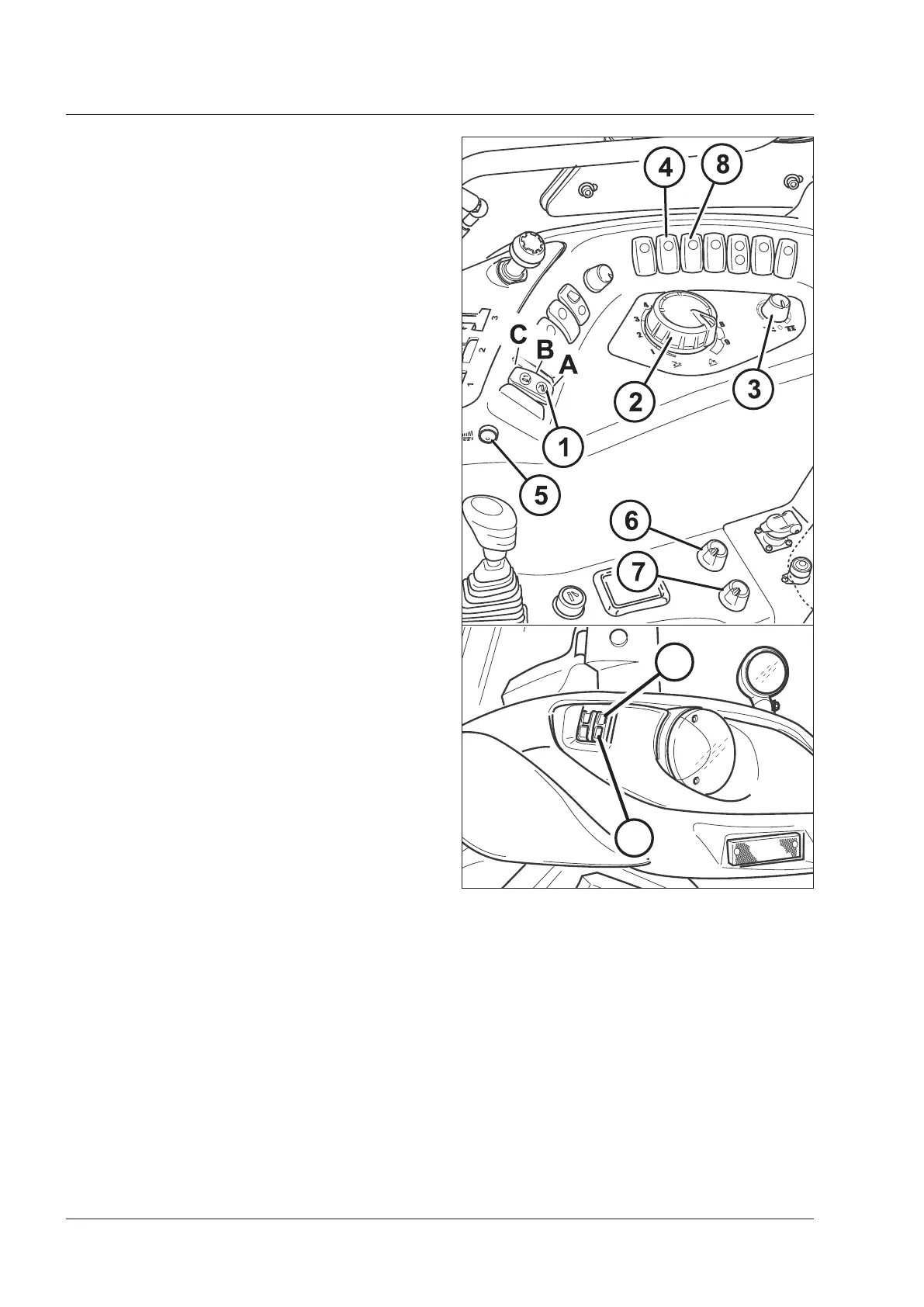
Control panel
1. 3-position up/down switch:
A: Lowering - Work position. This depends on the
settings of the controls (3 and 2).
B: Stop - The lift links are unable to move in any way
in the stop position.
C: Lifting - Transport: the fully raised position is estab-
lished by the limiter (7).
2. Implement work depth/height control:
0 - Low.
10 - Max height from ground.
3. Function selector:
– Position Control, turned anti-clockwise.
– Draft Control, turned clockwise.
– Intermediate positions: mixed Draft and Position
Control (INTERMIX).
4. Button and indicator light for damping function en-
gaged in transport position
5. Quick soil engagement button.
6. Down speed selector:
0: Does not go down. Lock - Turned in anti-clockwise
direction.
7. Maximum height limiter:
– Minimum height, turned in anti-clockwise direction.
– Maximum height, turned in clockwise direction.
8. Button to engage the slip control function, two posi-
tions:
ON - Slip Limit Activated
ON - Slip limit not activated
9. Hitch links up button.
10. Hitch links down button.
NOTE: The buttons 9 and 10 are installed on both mud-
guards.
Fig.5-31
9
10
 Loading...