Operation
5-61
5
P/N 6525032M1 - X6
HYDRAULIC CONTROL VALVES
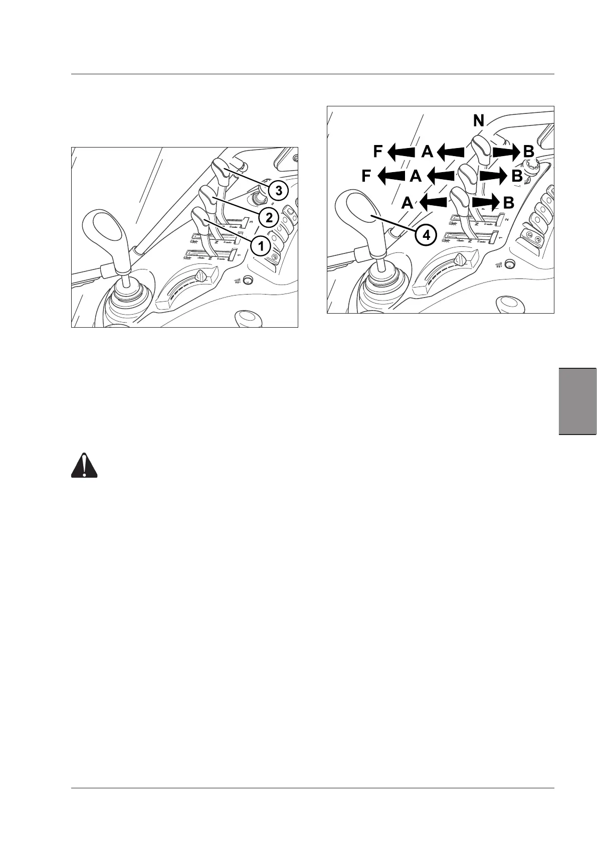
Control valve levers operate the corresponding valve:
lever 1 operates valve number 1, lever 2 operates valve
number 2 and so on.
NOTE: Oil level in the transmission should be checked
frequently for a regular operation of the hydraulic system.
If the external circuits draw too much oil, oil should be
topped up as described in the section 9 of this manual.
WARNING: The hydraulic rams of the implements be-
ing hitched to the tractor contain the same oil used in
the transmission of the tractor. This excludes any oil
contamination that could cause malfunction.
WARNING: The tractor engine must only be
started with the auxiliary control valve levers
in neutral position.
IMPORTANT: As the auxiliary control valves have differ-
ent configurations according to specific requirements of
the user, please ask your Argo Tractors Dealer for details
about the proper and safe use of hydraulic equipment.
The joystick 4is used with two auxiliary control valves.
If shifted forward, it controls the first valve, and laterally
the second one.
Lever locking device, with three positions
– If turned down and anti-clockwise, it prevents any
shifting of the lever to the neutral position.
– If turned clockwise to a middle position, it allows a to
and fro movement to control a single valve. Pull the
locking device up and shift the lever to the side to
control the second valve.
– If turned fully clockwise, the lever can be moved in all
directions to control both valves.
Control-valve operation
– Standard valve.
The control lever, automatically returns to the neutral
position (N) if shifted to the (A or B) positions, locking
the implement in the position assumed.
– Control valve with automatic release (kick-out)
The control lever remains locked in the assumed posi-
tion if shifted to the 'A' and 'B' positions.
Once the cylinder reaches the end of stroke, the pres-
sure automatically releases the lever and returns it to
the neutral position (N).
You can also manually return the lever to neutral posi-
tion before the cylinder reaches the end of its stroke.
– Control valve with floating position: this mode of op-
eration is designed for implements that normally rest
on the ground or that follow the relief of the ground
(e.g. graders, snow-ploughs, etc.). To select the float
position, push the control lever (1) to the second catch
in the 'F' position, where it stays without being held.
– Specific control valve for use with hydraulic motors.
NOTE:Do not use the control valve for hydraulic motors to
supply single/double-acting cylinders to avoid any risks of
accidents when using the connected hydraulic equipment.
 Loading...