Operation
5-67
5
P/N 6525032M1 - X6
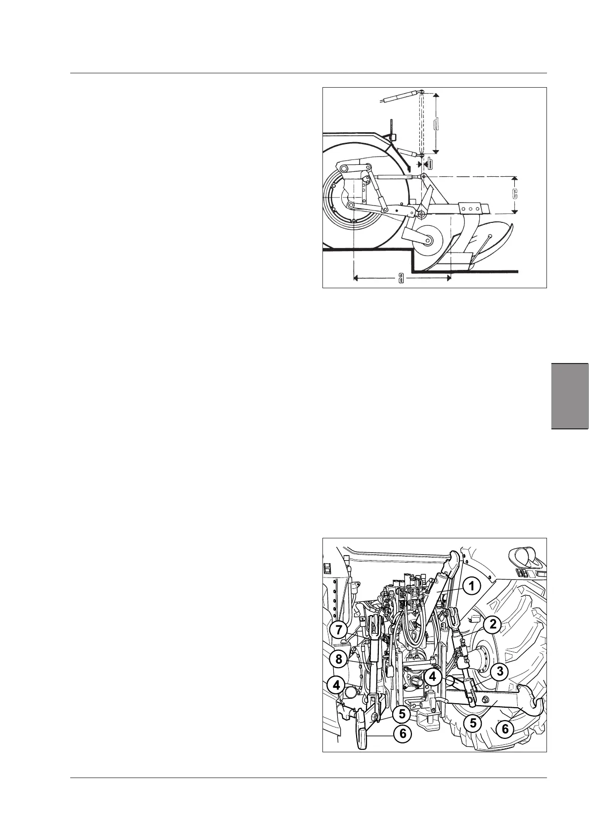
Fig.5-36 Implement coupling dimensions
a = Horizontal distance between lower link pins of the
three-point linkage and the implement's centre
of gravity.
As small as possible (the greater is the weight of
the implement, the smaller it is).
b = Third point backing: mm 0-80;
c = Hitch triangle height mm 460;
d = Drawbar length: mm 825±1.5.
NOTE: the plough in the figure is purely an example, as
the dimensions are valid for every implement type.
WARNING: Always use the specific PPE for the opera-
tion concerned. Beware of burns caused by hot tractor
and engine parts.
Implement hitching device
The three-point hitch connects the tractor to implements
controlled by the hydraulic hitch.
The articulated towing attachment with three-point linkage
is suitable for connection to 2
nd
class implements accord-
ing to the diagrams and data in Fig.5-36.
Implement attachments
For a correct operation of the hitch, check carefully the
dimensions of the implements that are to be coupled to
the tractor.
These couplings must have the same standardisation of
the tractor's three-point hitch to avoid that while working,
the unit is submitted to irregular stresses due to incom-
patible dimensions.
Weight of the implement
In order not to affect the regular operation of the hitch
system, implements should have a lower weight than the
maximum lifting capacity of the hitch. This value (men-
tioned in the technical specifications) is but a mere indica-
tion, as a great influence is also due to the distance of the
implement centre of gravity from the three-point hitch.
In fact, if an implement, though it weighs less than indi-
cated, is too far from the tractor, it will weigh down on
the three-point hitch with a much greater force than the
implement's own weight.
Three-point linkage
The articulated device with three-point linkage is essen-
tially composed of the following organs (Fig.5-37).
Lower links
The lower links (1) transmit to the implement the lugging
and support power. Various types are available:
- lower links with fixed ball ends;
- lower links with quick couplings.
Fig. 5-37
1. Top link with length adjustment sleeve
2. Rh vertical rod with adjuster device.
3. Adjustable fork of right-hand lift rod.
4. Lateral stabilisers (2 pcs)
5. Lower links
6. Hitch couplings
7. Adjustable fork of left-hand lift rod.
8. Left-hand lift rod.
Fig. 5-37 (indicative image, not comprehensive of all pos-
sible cases)