TD 93021US
17 July 2017 / Ver. PF3 111
Installation Guide
teleCARE IP
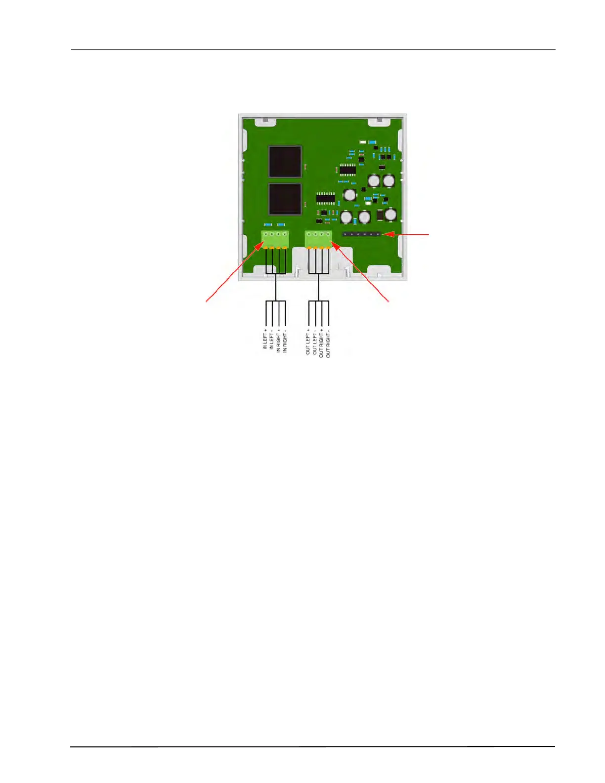
6.17.1 Television Interface Module Electrical Connections
Figure 152. Television interface module electrical connections
Note:
• The equipment that is connected to this interface is not considered to be part of the system
configuration unless the equipment complies with ANSI/UL 2560 standard for Emergency Call
Systems for Assisted Living and Independent Living Facilities.
• The Television Interface Module provides electrical isolation between the Television and the
teleCARE IP Emergency Call System.
• Television audio in teleCARE IP requires the bedside module NIBM2. For details of the NIBM2 refer
to chapter 6.5“Bedside Module (NIBM2)” on page 68.
• The 4 pole connector terminals must be ordered separately.
J3: Not used.
J1: TV Stereo
Audio Input from
the Television
Headphone Jack
Socket
J2: TV Stereo Audio
Output to the
teleCARE IP