TD 93021US
17 July 2017 / Ver. PF3 180
Installation Guide
teleCARE IP
8.7.7 NILF DIP Switch Settings
The NILF uses three sets of 8-pole DIP switches to set the ID, output power and transmission rate, master/
slave mode and the active location functionality.
NILF ID
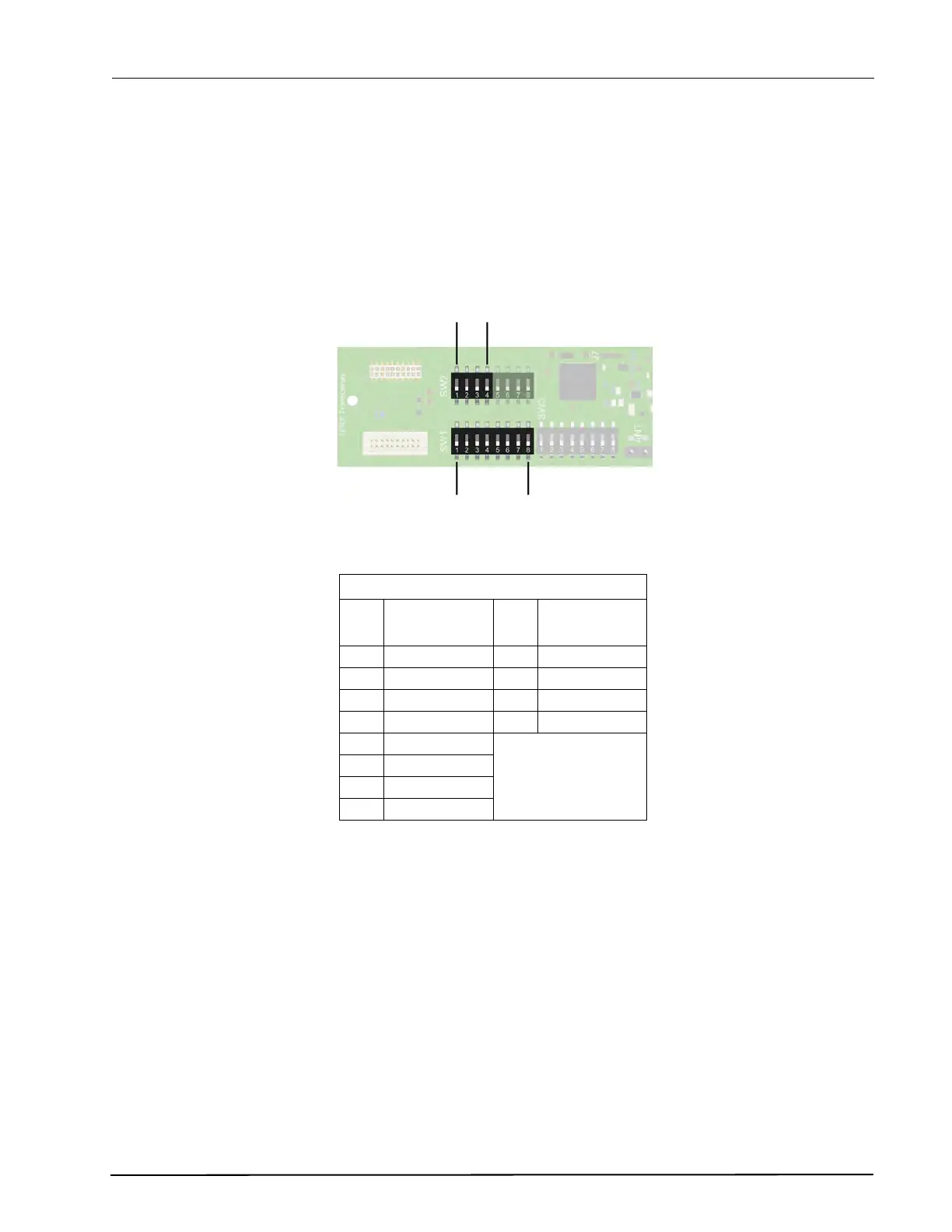
DIP switches SW1 (1-8) and SW2 (1-4) are used to set the 12 bit ID code of the NILF.
Figure 240. NILF 12 bit ID - DIP switch settings
* When the highest bit (bit 11) of the NILF ID is set the NILF will function as an active location beacon.
See “Beacon Mode” on page 183. for detailed information.
NILF ID Settings
SW
1
Low byte SW
2
High nibble
1Bit 0 1Bit 8
2Bit 1 2Bit 9
3 Bit 2 3 Bit 10
4 Bit 3 4* Bit 11
5Bit 4
6Bit 5
7Bit 6
8Bit 7
SW 2 - bit 8 to 11
SW 1 - bit 0 to 7