TD 93021US
17 July 2017 / Ver. PF3 70
Installation Guide
teleCARE IP
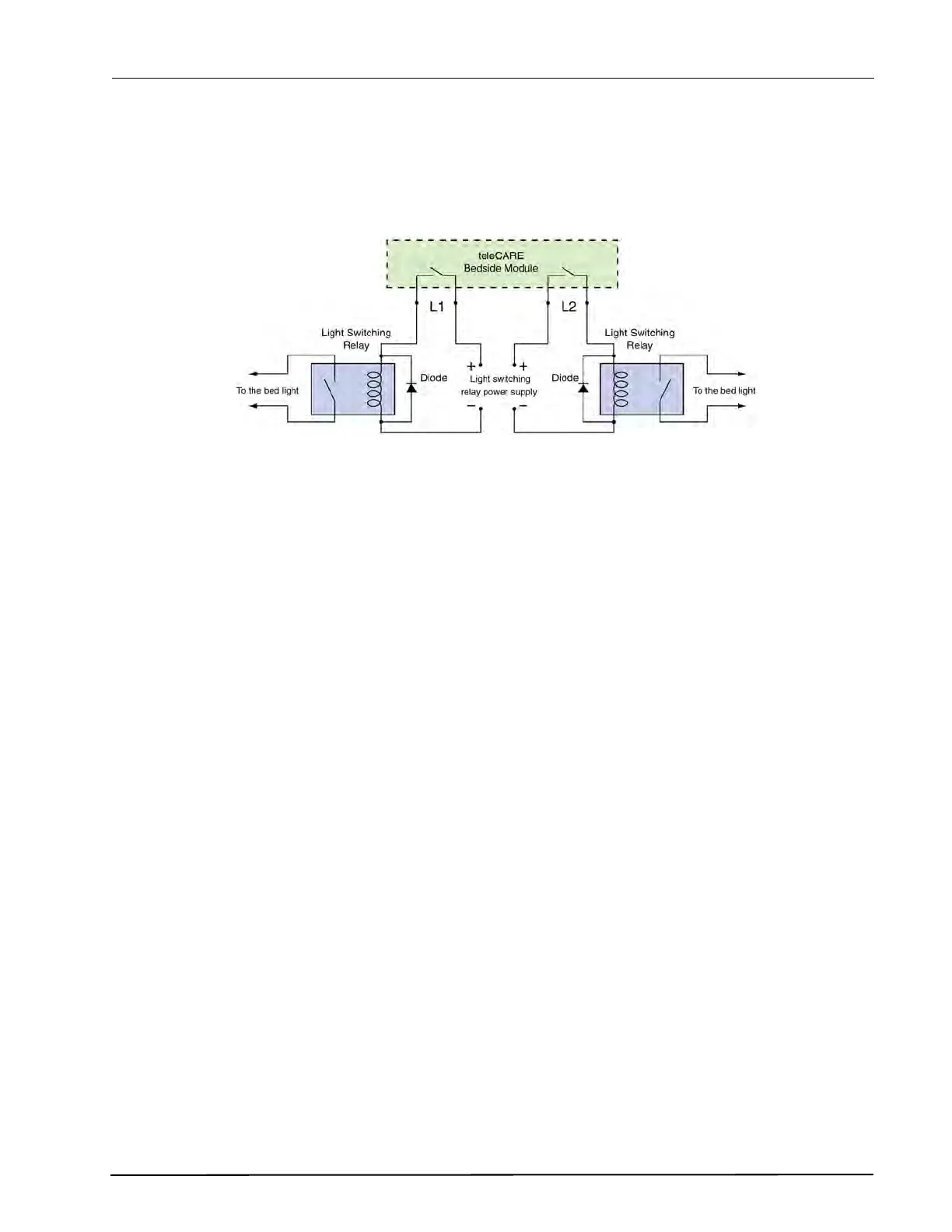
6.5.2 Light Switching Relay Maximum Load and Surge Damping Diode
The teleCARE switch module NIBM2 with a socket and bed light control include 2 light switching circuits.
Each circuit is suitable for switching a bi-stable 24Vdc relay. The maximum switching current for each
relay must not exceed 0.3A at maximum 30Vdc.
Figure 92. Light switching relay with surge damping diode
WARNING:
• The equipment that is connected to this interface is not considered to be part of the system
configuration unless the equipment complies with ANSI/UL 2560 standard for Emergency Call
Systems for Assisted Living and Independent Living Facilities.
• Do not connect the bed light circuitry directly to the L1 and L2 switch contacts on the NIBM2.
• The Light Switching Power Supply and Relay must be UL listed or recognized components.
• The maximum switching current for the L1 and L2 contacts on the L1 and L2 contacts on the
NIBM2 must not exceed 0.3A at 30Vdc.
• A diode (1N4004 or equivalent) must be connected across the coil of the bed light switching relay
to prevent surges caused by the relay coil.