TD 93021US
17 July 2017 / Ver. PF3 62
Installation Guide
teleCARE IP
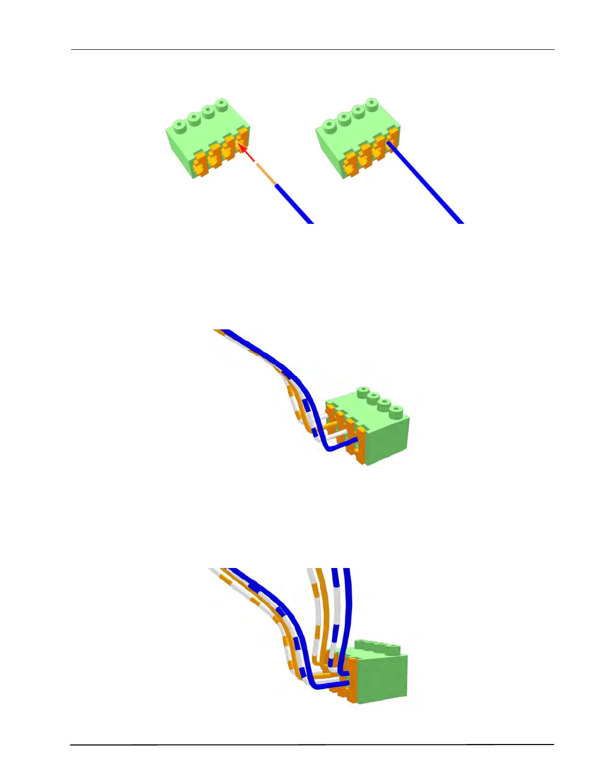
Figure 78. Inserting a wire in the connection point
Check that a good connection has been made by gently pulling on the wire after it has been inserted.
The wire should stay fixed in the terminal.
Four wires are required for the room bus, passive bus and light relay outputs, so repeat the above
illustrated procedure on the remaining three wires.
Figure 79. Connector terminal complete with four wires
6.4.4 4-Pole Connector Terminal with Looped Wiring
In cases where the cable loops from peripheral to peripheral (with incoming and outgoing wiring) one set
of wires should be inserted in the top connection points and the other set in the lower connection points,
as shown in the following illustration:
Figure 80. Connector terminal with looped wiring