TD 93021US
17 July 2017 / Ver. PF3 91
Installation Guide
teleCARE IP
6.12.11 Mounting the NIPC2 Pull Cord Module to the Backplate
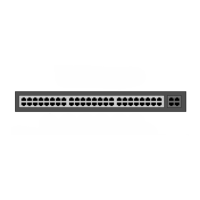
The method described for mounting the switch module to the backplate is basically the same for the
active and the passive pull cord switch modules. The following illustration shows the back plate mounted
on the back box with the cable pulled through and connected to the 4-pole connection terminal.
Figure 123. Cable of the pull cord module with the 4-pole connector
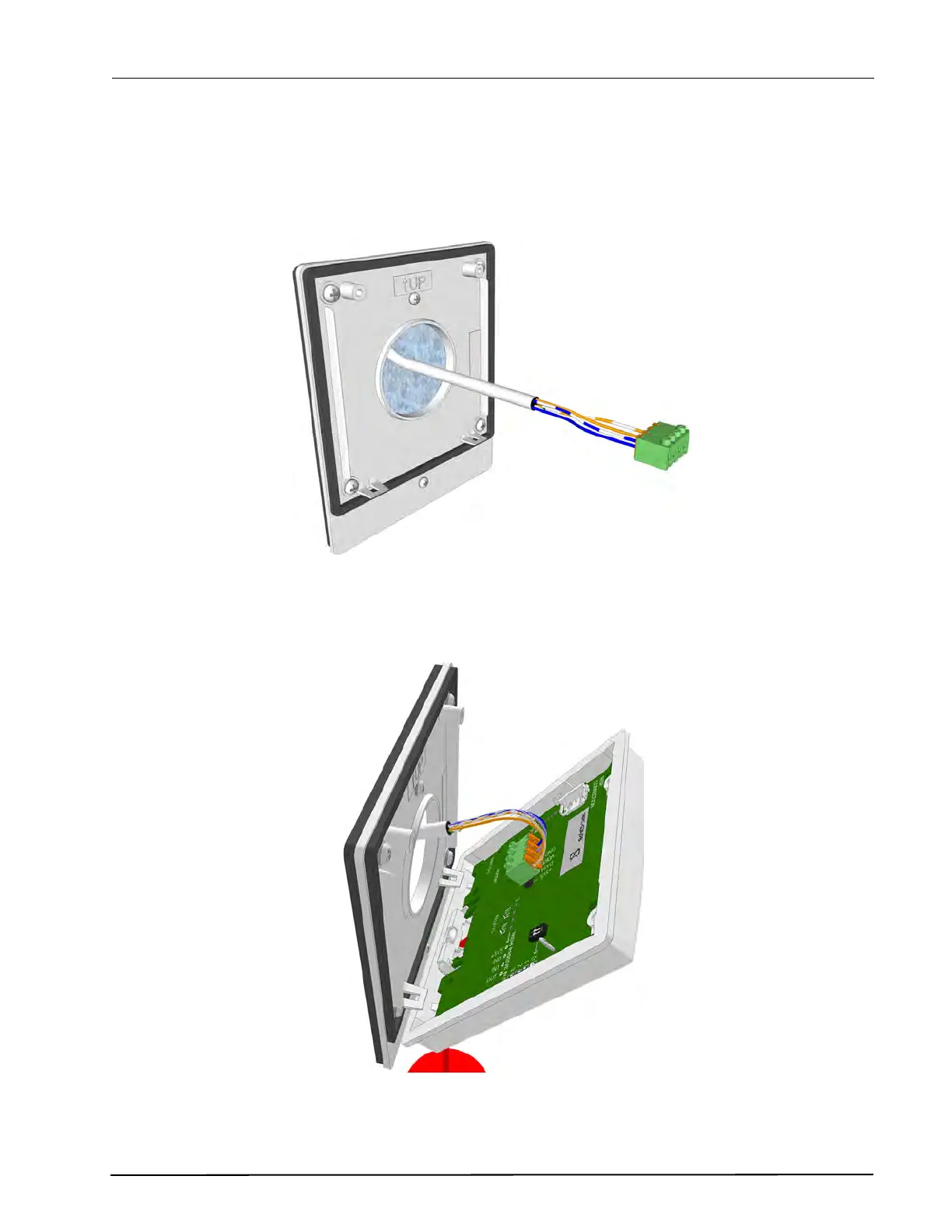
Plug in the connection terminal to the appropriate 4-pin connector of the pull cord module (active =
room bus connector, passive = passive bus connector).
Figure 124. Connecting the room bus to the switch module