17 July 2017 / Ver. PF3 116
TD 93021US
Installation Guide
teleCARE IP
Peripherals
7.5 Connection Board
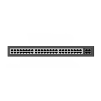
The NICB has two connectors: a 5-pole connector for connection to the cross cable and a
4-pole connector (NICT4-AA) for connections to the external inputs. The following figure
shows the connections.
Figure 159. Connections on the NICB
7.5.1 4-Pole Connector Terminal
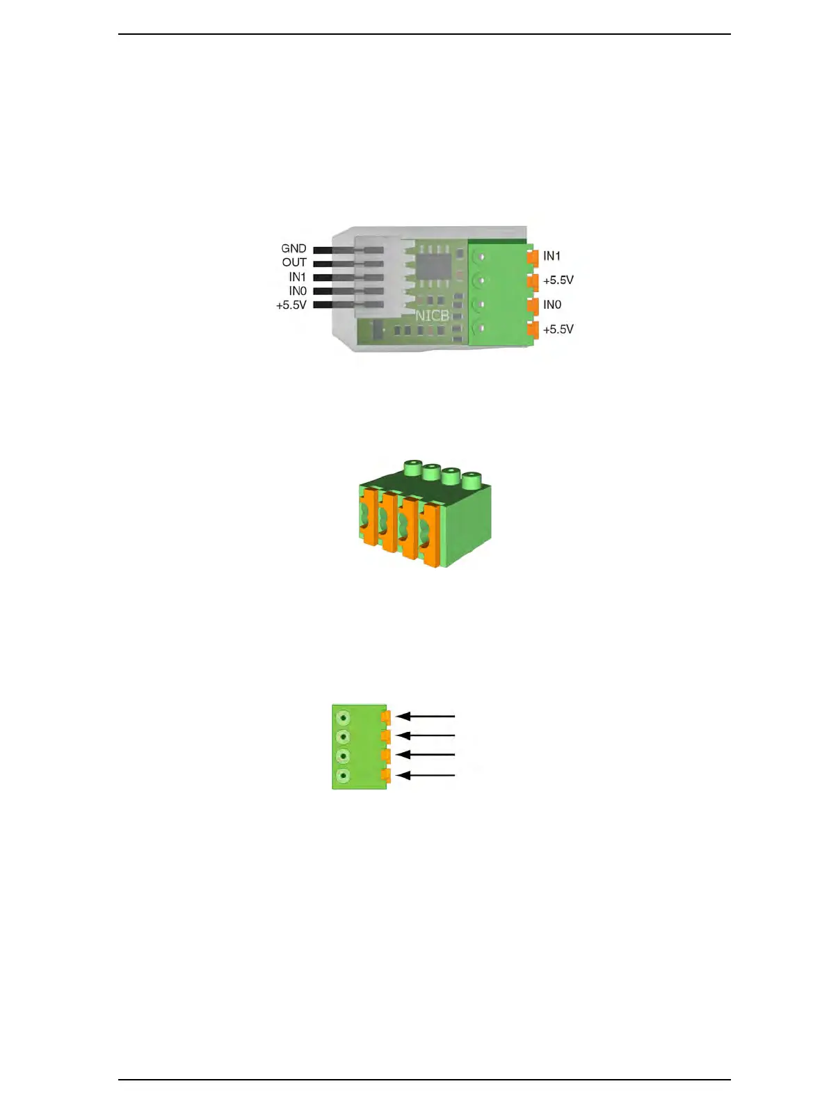
Figure 160. 4-pole connector terminal
The NICB kit (NICB-AAA) contains a 4-pole connector terminal (NICT4-AA). It has a
screwless “spring-cage” connection technique and each terminal has two connection
points. See “4-Pole Connector Terminal” on page 60.
The designation of the external inputs is shown in the following figure.
Figure 161. 4-pole connector terminal with the inputs.
7.5.2 External Contacts
The external connections (+5.5V, IN0, and IN1) can be used to monitor potential-free dry
relay contacts, such as a door open contact or a passive infra-red (PIR) contact. The
external contacts can be “normally open” or “normally closed”. The functionality of the
monitoring connections is configured in the System Manager (NISM2).