TD 93021US
17 July 2017 / Ver. PF3 65
Installation Guide
teleCARE IP
6.4.8 Dismantling the Switch Modules
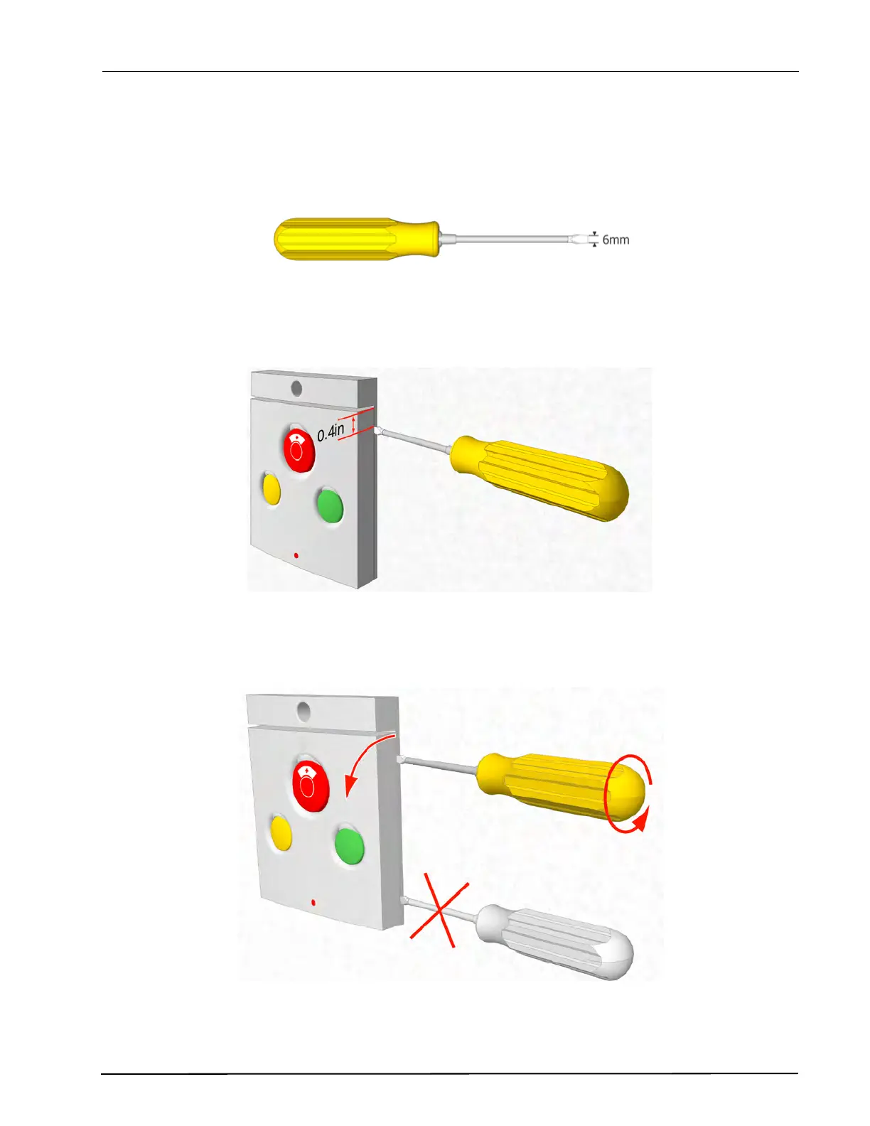
To separate the switch module from the backplate, a screwdriver with a point of approximately 0.25in
(6mm) wide should be used.
Figure 84. Suitable screwdriver for dismantling switch modules
Insert the point of the screwdriver into the groove at the side of the switch module between the faceplate
and the back plate at about 0.4in (10mm) down from one of the top corners.
Figure 85. Inserting the screwdriver
Gently push and turn the screwdriver until the switch module releases from the back plate.
Figure 86. Removing the switch module from the back plate
Note: Do not insert the screwdriver into the bottom corner of the faceplate.