TD 93021US
17 July 2017 / Ver. PF3 181
Installation Guide
teleCARE IP
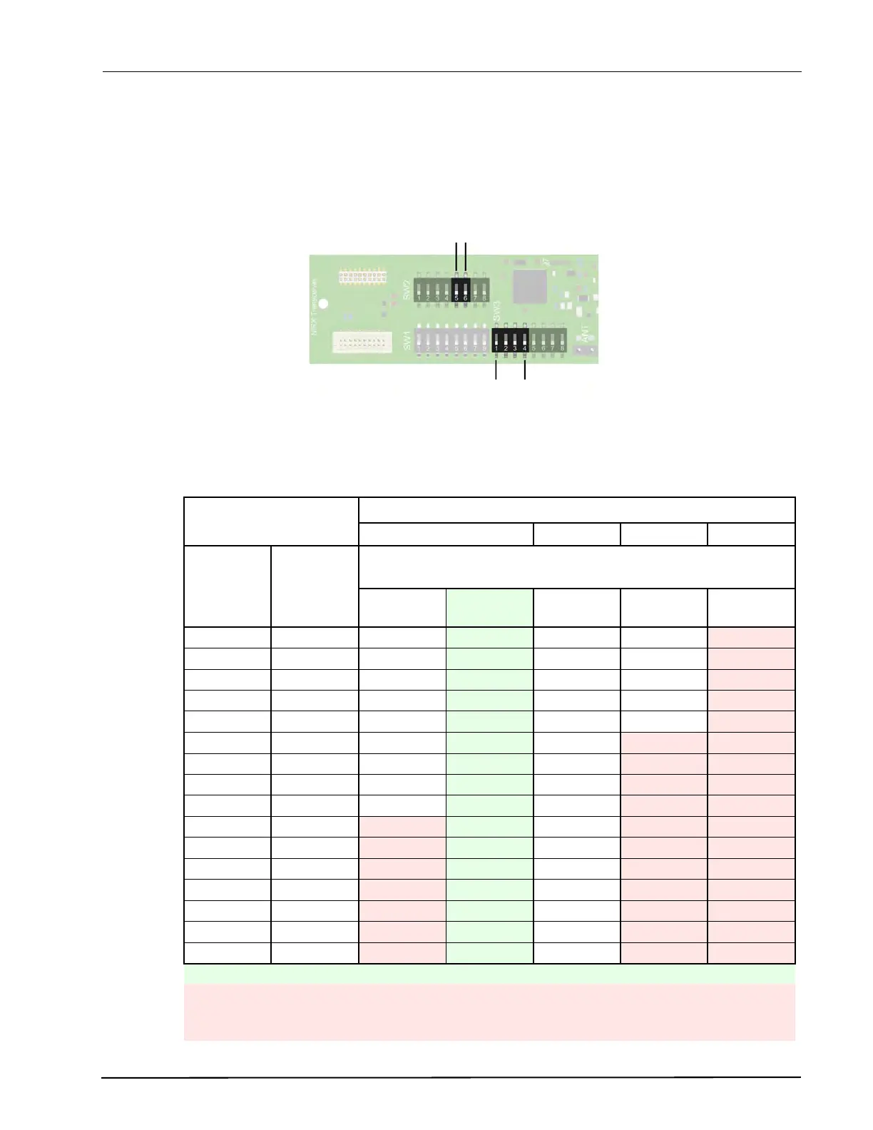
Output Power and Transmission Rate DIP Switch Settings
With the 4 bit output power DIP switch SW3 (1-4) selection the range of the LF field can be adjusted. In
relation with the output power, the repetition rate of the low frequency transmissions can be set to
normal, high, low and very low using 2 bit DIP switch setting on SW2 (5 and 6).
Figure 241. Output Power and Repetition Rate DIP switch settings
Lowering the output power to decrease the range of the LF field will increase the repetition rate of the
transmissions. The table below shows the relation between the output power and the repetition rate:
Output Power Repetition Rate (transmissions/s)
Normal High Low Very Low
SW3
(4 - 1)
Range
(m)
SW2
(6 - 5)
00
Battery
Life (years)
01 10 11
0000 0.3 10
3.7 20 5 1
0001 0.31 8
16 4 0.8
0010 0.36 6.7
13.4 3.35 0.67
0011 0.49 5.0
10 2.5 0.5
0100 0.63 4.0
4.8 8 2 0.4
0101 0.76 3.3
6.6 1.65 0.33
0110 0.94 2.7
5.4 1.35 0.27
0111 1.08 2.4
6.2 4.8 1.2 0.24
1000 1.21 2.1
4.2 1.05 0.21
1001 1.44
1.8 3.6 0.9 0.18
1010 1.53
1.7 5.5 3.4 0.85 0.17
1011 1.71
1.5 3 0.75 0.15
1100 1.93
1.3 4.1 2.6 0.65 0.13
1101 2.16
1.2 2.4 0.6 0.12
1110 2.43
1.1 2.2 2.2 0.55 0.11
1111 2.7
1.0 1.5 2 0.5 0.10
Battery life indication is only applicable for “Normal” repetition rate settings.
The repetition rate in the red marked areas are only applicable for “Passive” location beacons.
“Active” location beacons will always have a repetition rate of at least 2 transmissions a second.
Note that this also has an impact on the battery life.
Repetition Rate
SW 3
Output Power
SW 2
Repetition Rate