TD 93021US
17 July 2017 / Ver. PF3 39
Installation Guide
teleCARE IP
5.7.1 Auxiliary Lamp Connection - NILD2
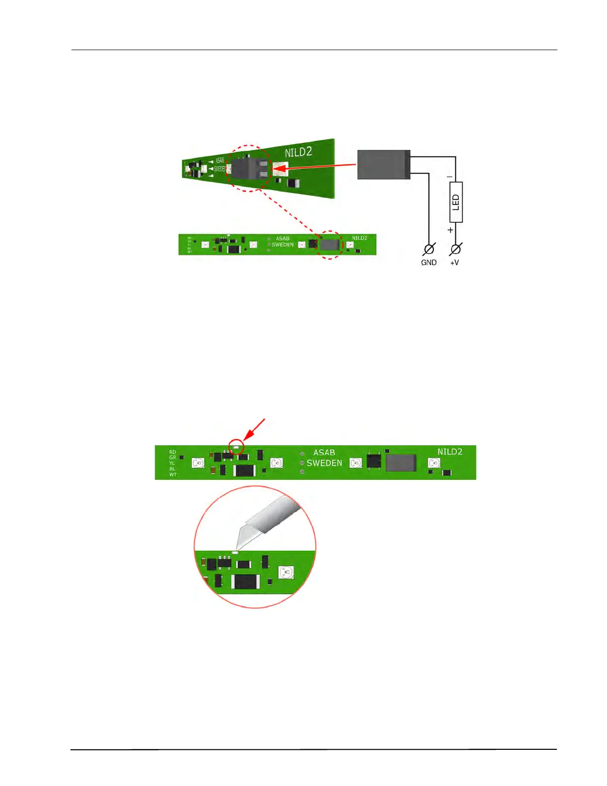
The green LED board (NILD2-GAA) has a galvanically isolated relay contact that can be used to connect to
an auxiliary lamp. It has a maximum switching capacity of 0.4A at 60V peak.
Figure 45. External corridor lamp connections through the NILD2-GAA
IMPORTANT: In order to retain the galvanic isolation, it is not allowed to connect the
GND(-) of the auxiliary power supply to the GND (-) of the NIRC3.
Disabling the LEDs
If the relay contact only is required, without the green LED on the NILD2-GAA board, then the conductor
track should be cut through at the break point to disable the LEDs, as shown in the following illustration:
Figure 46. Disabling the LEDs of the NILD2-GAA
To auxiliary power supply
Max. 0.4A at 60V peak
NILD2