TD 93021US
17 July 2017 / Ver. PF3 22
Installation Guide
teleCARE IP
5.2.4 Installing the Room Controller
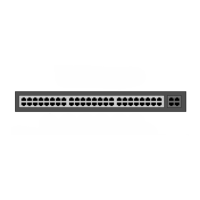
When installing the Room Controller the first step is to separate the top section (cover, PC board, and
lamp dome) from the housing. To do that simply grip the top edge of the cover and pull it away from the
housing, as shown in the following illustration:
Figure 14. Separating the top section from the housing
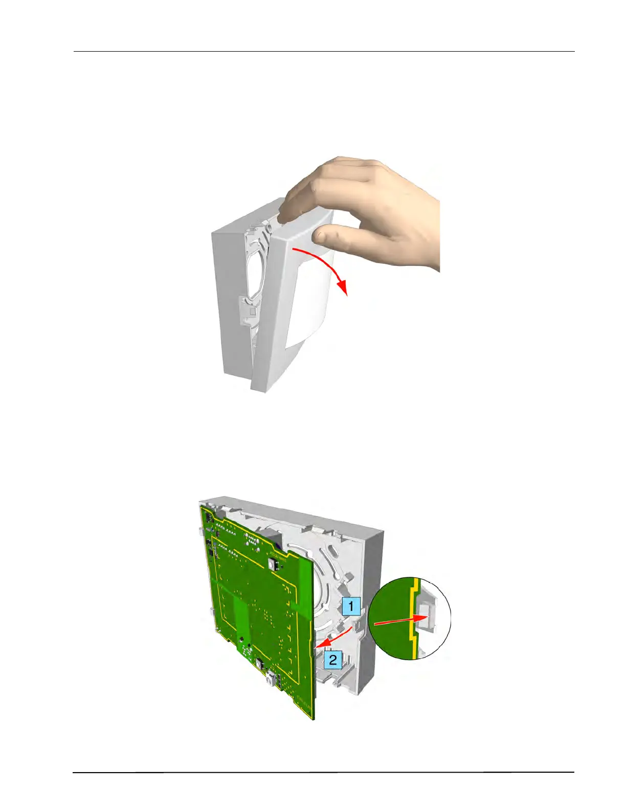
5.2.5 Removing the Room Controller Printed Circuit Board
To remove the circuit board from the housing, press the holding clip outwards until it releases the circuit
board (1). With the printed circuit board released from the holding clip, slightly pivot the circuit board (2)
and remove the board from the housing, as shown in the following illustration:
Figure 15. Removing the circuit board from the housing