TD 93021US
17 July 2017 / Ver. PF3 143
Installation Guide
teleCARE IP
NUREP Electrical Connections
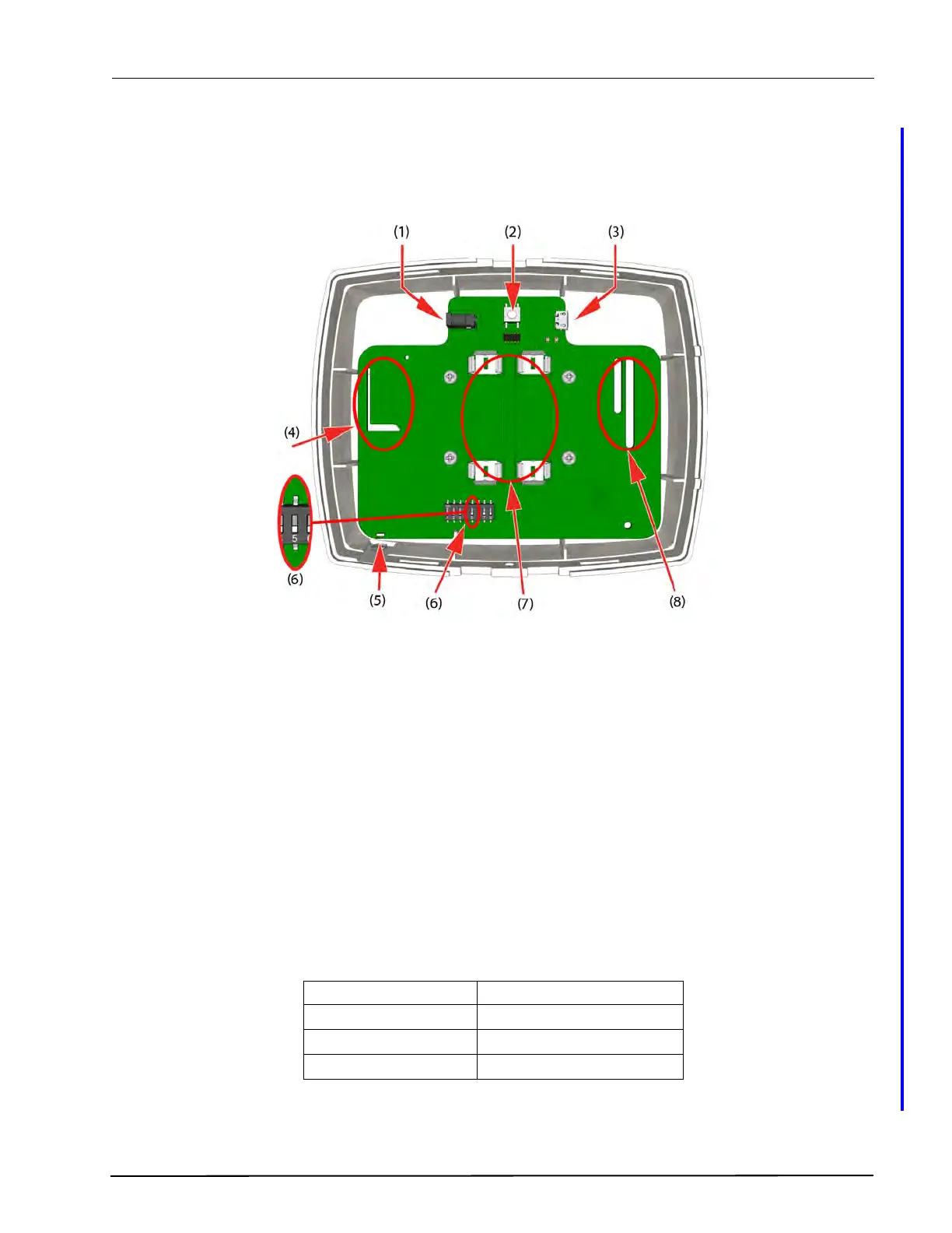
The figure below shows the electrical connections of the wireless repeater (NUREP).
Figure 183. NUREP electrical connections
(1) 5VDC power connector - For connecting the supplied 5VDC Class II power adapter
(2) Reset switch
(3) Micro USB connector - Not applicable
(4) Internal RF antenna section - For RF (916 to 921 MHz) communication with wireless
modules
(5) Multi color status LED, see the “Status LED colors” table below
(6) 8 pole DIP switch - Mode:
SW5 off - Wireless Repeater
SW5 on - Wireless Gateway
(7) Battery connection - Optional, for placing two AA type 1.5V alkaline batteries
(8) Internal RF antenna section - For RF (IEEE 802.15.4) communication between
repeaters
Table 9. Status LED colors
NIRC3 - Status color Status
Steady blue Normal operation
Steady green Searching for 2G4 network
Steady Red Error