TD 93021US
17 July 2017 / Ver. PF3 32
Installation Guide
teleCARE IP
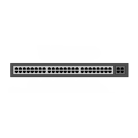
Figure 31. Inserting a wire in the connection point
Check that a good connection has been made by gently pulling on the wire after it has been inserted.
The wire should stay fixed in the terminal.
Four wires are required for the room bus, passive bus, and light relay outputs, so repeat the above
illustrated procedure on the remaining three wires.
Figure 32. Connector terminal complete with four wires
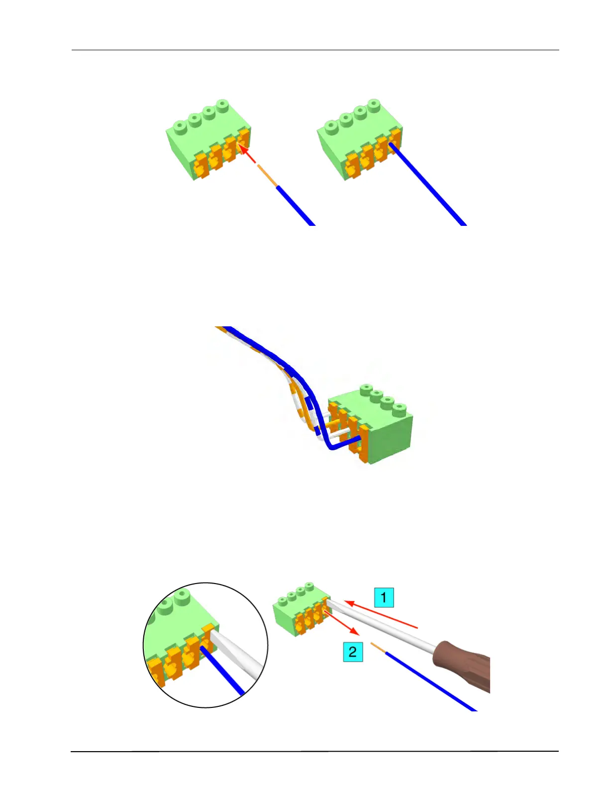
Disconnecting a Wire from the Connector Terminal
First carefully place the point of a small screw driver (point approximately 0.1in (2.5mm) wide) on the
relevant orange colored release key of the connection terminals and press the key in firmly to open the
spring-cage connector (1). With the release key pressed in pull the wire from the terminal (2) then remove
the screw driver.
Figure 33. Removing a wire from a connection point