TD 93021US
17 July 2017 / Ver. PF3 90
Installation Guide
teleCARE IP
6.12.10 Passive Pull Cord Module Electrical Connections
The NIPC2 WAP is a passive teleCARE IP peripheral which must be connected to the passive bus of a door
side module or a toilet cancel module.
Refer to section 6.4.2, Preparing the Wires for the 4-pole Connector Terminal on page 61). in order to
correctly strip the cable and prepare the wires for the 4-pole connector.
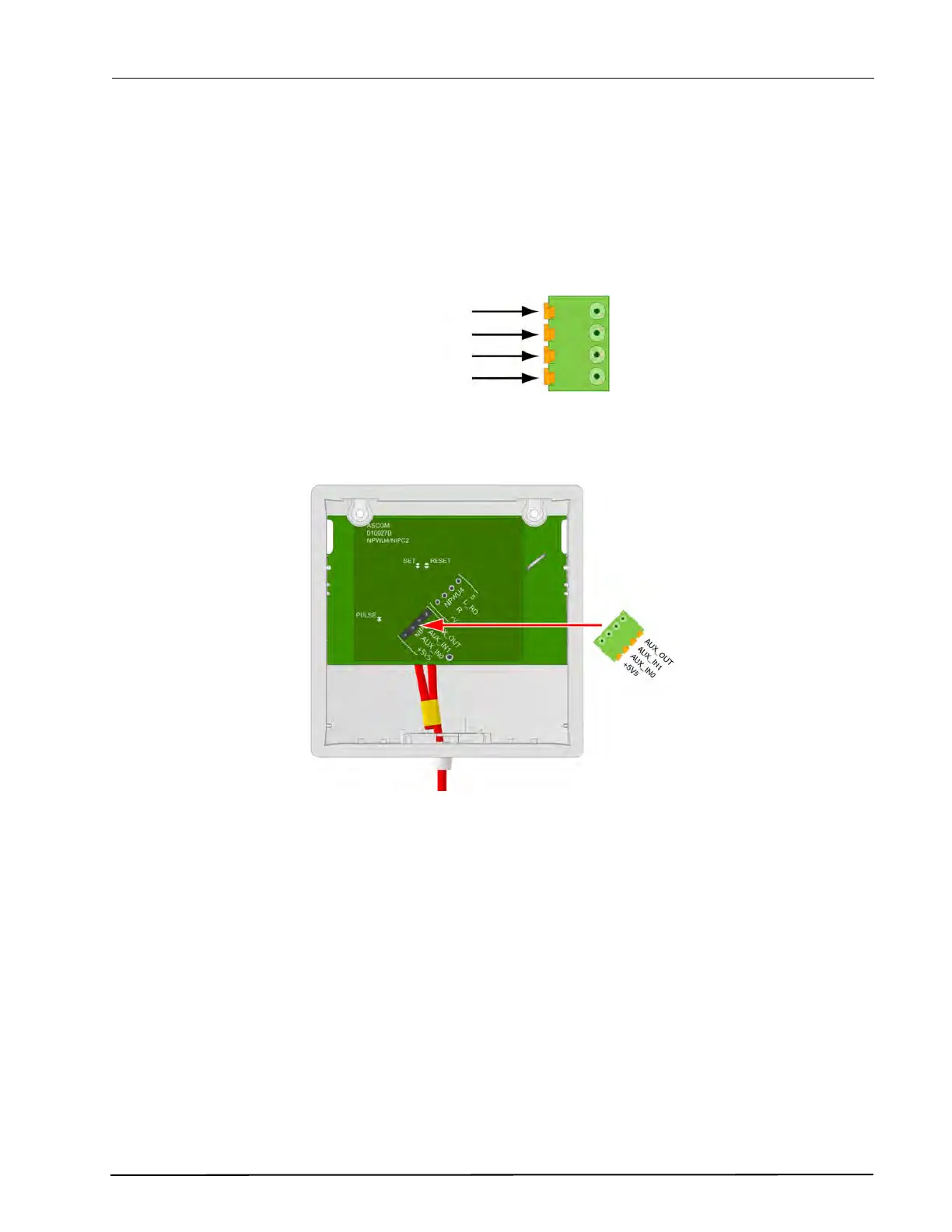
The connections of the passive bus wires is shown in the following illustration.
Figure 121. 4-pole connector terminal with the passive bus
The illustration below shows the location of the passive bus connector:
Figure 122. Passive bus connector location
5.5Vdc
(Aux) IN0
(Aux) IN1
(Aux) OUT
4-Pole
Connector
for the
Passive
Bus