TD 93021US
17 July 2017 / Ver. PF3 45
Installation Guide
teleCARE IP
With the printed circuit board released from the holding clip, partly rotate the circuit board and remove it
from the housing.
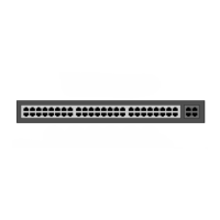
5.8.3 Corridor Lamp Housing
The corridor lamp has the same housing as used for the IP room controller which is designed to be
surface mounted. Refer to section 5.2.6, Room Controller Housing on page 23 for details of mounting
the housing.
Figure 56. IP room controller housing
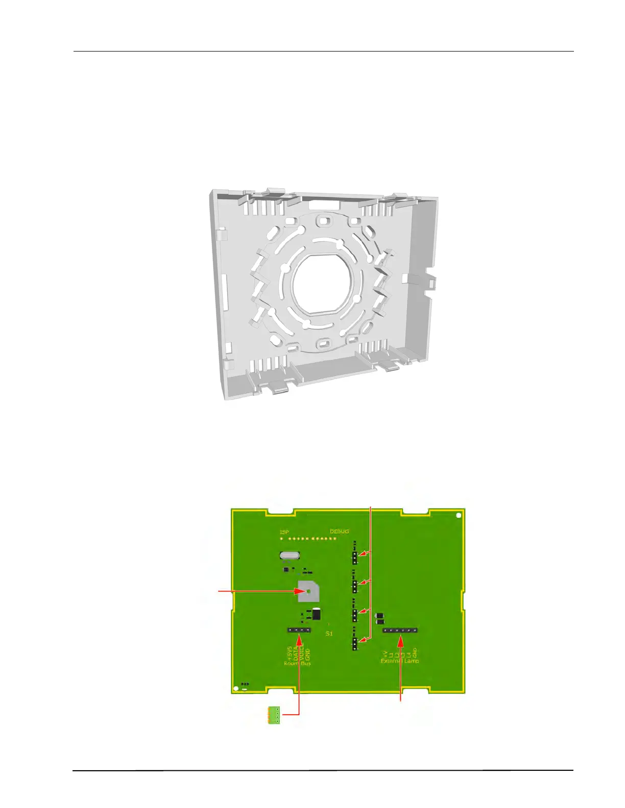
5.8.4 NICL2 - Corridor Lamp Electrical Connections
The wiring between NIRC3 and the NICL2 Corridor Lamp consists of the teleCARE IP four-wire room bus.
Figure 57. NICL2 - Corridor lamp PCB component side electrical connections
LED Lamp
Through-Board
Connectors
Buzzer
Room Bus
(from the
Room Controller)
Input Connector
for Passive LED
mode