TD 93021US
17 July 2017 / Ver. PF3 179
Installation Guide
teleCARE IP
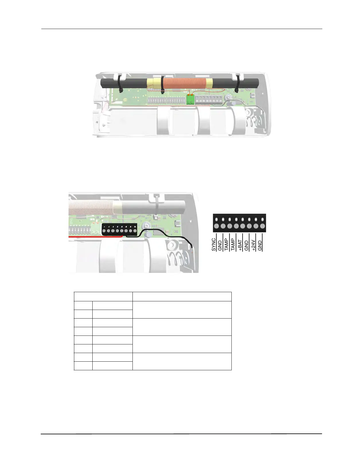
Antenna Connection
The 2-pole antenna connection (J3) is connected to the internal LF antenna.
Figure 238. NILF internal antenna connected
External Connections
The 8-pole external connector (J2) has connections for a second beacon (used for range extending in a
master/slave configuration), a galvanically separated tamper alarm relay output, the internal battery and
connection of an alternative external 24Vdc power supply.
Figure 239. External connections - J2
For master / slave connection see “Master / Slave Beacon Interconnection” on page 182.
For tamper alarm relay connection see “Tamper Alarm” on page 184.
For 24Vdc external power supply, use only a certified ECS power supply (see Section 4.).
External Connector Description
1SYNC
Master / Slave interconnection
Beacon synchronization
2GND
3TAMP
Tamper alarm relay output
(galvanically separated)4TAMP
5+BAT
Battery connection
6GND
7 +24V
External 24Vdc power supply
connection8GND
 Loading...