TD 93021US
17 July 2017 / Ver. PF3 27
Installation Guide
teleCARE IP
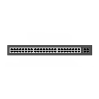
5.3.3 Room Controller (NIRC3) Printed Circuit Board Back View
Figure 22. NIRC3 printed circuit board back view
On the back of the NIRC3 printed circuit board there are four sets of through-board connection holes for
LED lamp boards. Details of for connecting the LED lamp boards are given in section 5.7, LED Lamp
Boards (NILD2), page 38.
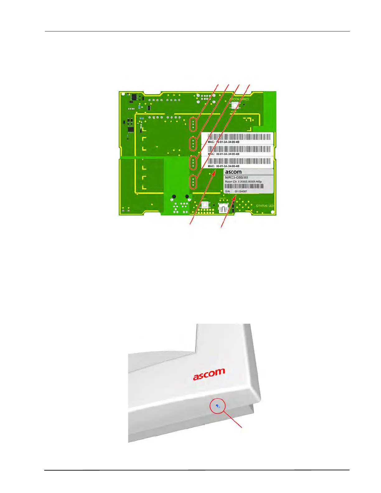
5.3.4 NIRC3 Status Information
The NIRC3 status information is visible through an LED that can be seen from the bottom of the NIRC3
housing.
Figure 23. NIRC3 Status LED
Product label with part number
and serial number
Through-Board Connection
Holes for the LED Lamp
MAC address label
NIRC3