TD 93021US
17 July 2017 / Ver. PF3 42
Installation Guide
teleCARE IP
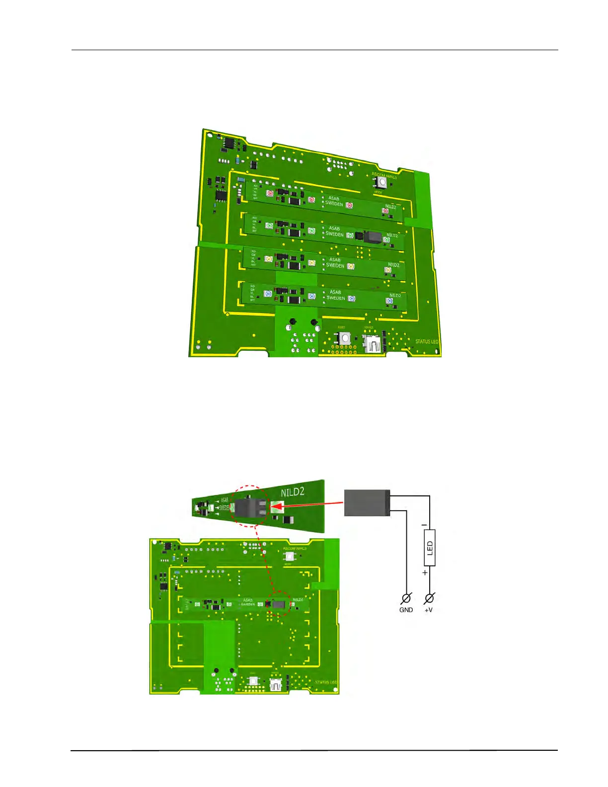
With the three pins inserted and the LED lamp board lined up with the guide marks, firmly press the LED
lamp board into the IP room controller PCB. Repeat the procedure on the other required LED lamp
boards.
Figure 50. NIRC3- room controller PCB with 4 LED lamp boards
Caution: The maximum load on each external LED circuit is 60mA.
5.7.4 Auxilliary Lamp Connection
The room controller (NIRC3) circuit board does not support an external corridor lamp directly, however an
external lamp can be connected through a green LED lamp board (NILD2-GAA) which has a galvanically
isolated relay contact available with a maximum switching capacity of 0.4A at 60V peak.
Figure 51. External corridor lamp connections through the NILD2-GAA
For detailed information “Auxiliary Lamp Connection - NILD2” on page 39.
NIRC3
To auxiliary power supply
Max. 0.4A at 60V peak
IMPORTANT: In order to retain
the galvanic isolation, it is not
allowed to connect the GND (-) of
the auxiliary power supply to the
GND (-) of the NIRC3.