TD 93021US
17 July 2017 / Ver. PF3 136
Installation Guide
teleCARE IP
Note: Refer to
“NILF DIP Switch Settings” on page 180
in order to adjust the configuration of
the NILF to suite the requirements.
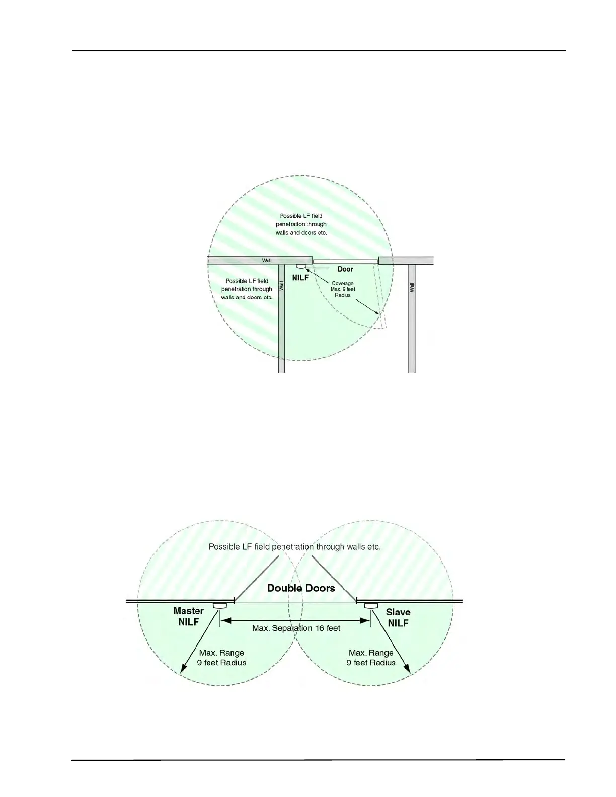
The NILF has a circular coverage distribution pattern in the horizontal plane. The coverage area has a
radius 9 feet radius from the NILF (free of obstructions), as shown in the following illustration. Reduced
signal strength is possible through walls of light weight construction.
Figure 177. Wall Mounted NILF horizontal coverage
Note: The LF signal can penetrate certain building materials which means the signal might
be detected through walls, doors and ceilings etc.
If an LF coverage area is to be over 9 feet wide (radius), a combination of “Master and Slave” NILF
beacons should be used. The maximum separation between the master and slave beacon is
approximately 16 feet.
The following diagram shows an example of the measurements which should be considered when
positioning “Master and Slave” NILFs.
Figure 178. Master and slave NILF coverage