Parts Identification
25
PLEASE READ WITHOUT
FAIL
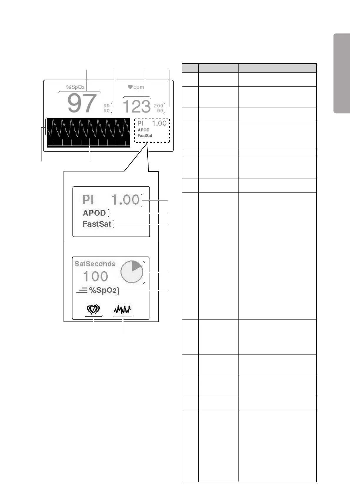
Description
Displays a detected SpO
2
value
digitally.
Displays an SpO
2
upper alarm
limit above and an SpO
2
lower
alarm limit below digitally.
Displays a detected pulse rate
digitally.
Displays a pulse rate upper
alarm limit above and a pulse
rate lower alarm limit below
digitally.
Displays the perfusion index.
Indicates the currently se-
lected sensitivity (Max, Nor-
mal, APOD).
Comes on when the FastSat
mode is ON.
The numerical value on the left
is the SatSeconds setting. The
circular indicator on the right
changes color little by little
clockwise each time a detected
%SpO
2
is found to be above the
%SpO
2
upper alarm limit or
below the %SpO
2
lower alarm
limit. When the whole indica-
tor has changed color, either
the SpO
2
upper limit alarm or
the SpO
2
lower limit alarm will
occur appropriately. The dis-
colored area will decrease little
by little counterclockwise each
time a detected %SpO
2
is found
to be within the acceptable
range.
❋1
Indicates that the response
mode is set to “Fast.” This in-
dicator will disappear when the
response mode is switched to
“Normal.”
Comes on when interference
is detected.
Comes on when no pulse is
detected.
Displays pulse waves.
Displays the Signal IQ (SIQ)
bar graph.
The height of each bar is in
proportion to the quality of the
input signal concerned. The
more reliable a measured
value is, the higher the bar
becomes. The less reliable a
measured value is, the lower
the bar becomes.
No.
q
w
e
r
t
y
u
i
o
!0
!1
!2
!3
Name
%SpO2
display
SpO2 alarm
limits display
Pulse rate
display
Pulse rate
alarm limits
display
PI display
Set sensitivity
indicator
FastSat
indicator
SatSeconds
display
❋
Fast Re-
sponse Mode
Interference
indicator
(Nellcor only)
Pulse search
indicator
(Nellcor only)
Pulse waves
display
SIQ display
(Masimo
only)
e
q
w
r
!2
!3
TheunitprovidedwiththeMasimo
pulseoximeter
TheunitprovidedwiththeNellcor
pulseoximeter
i
o
!1
!0
t
y
u
[Pulse area]
❋ Touch this area to start the pulse oximeter-related setting operation.