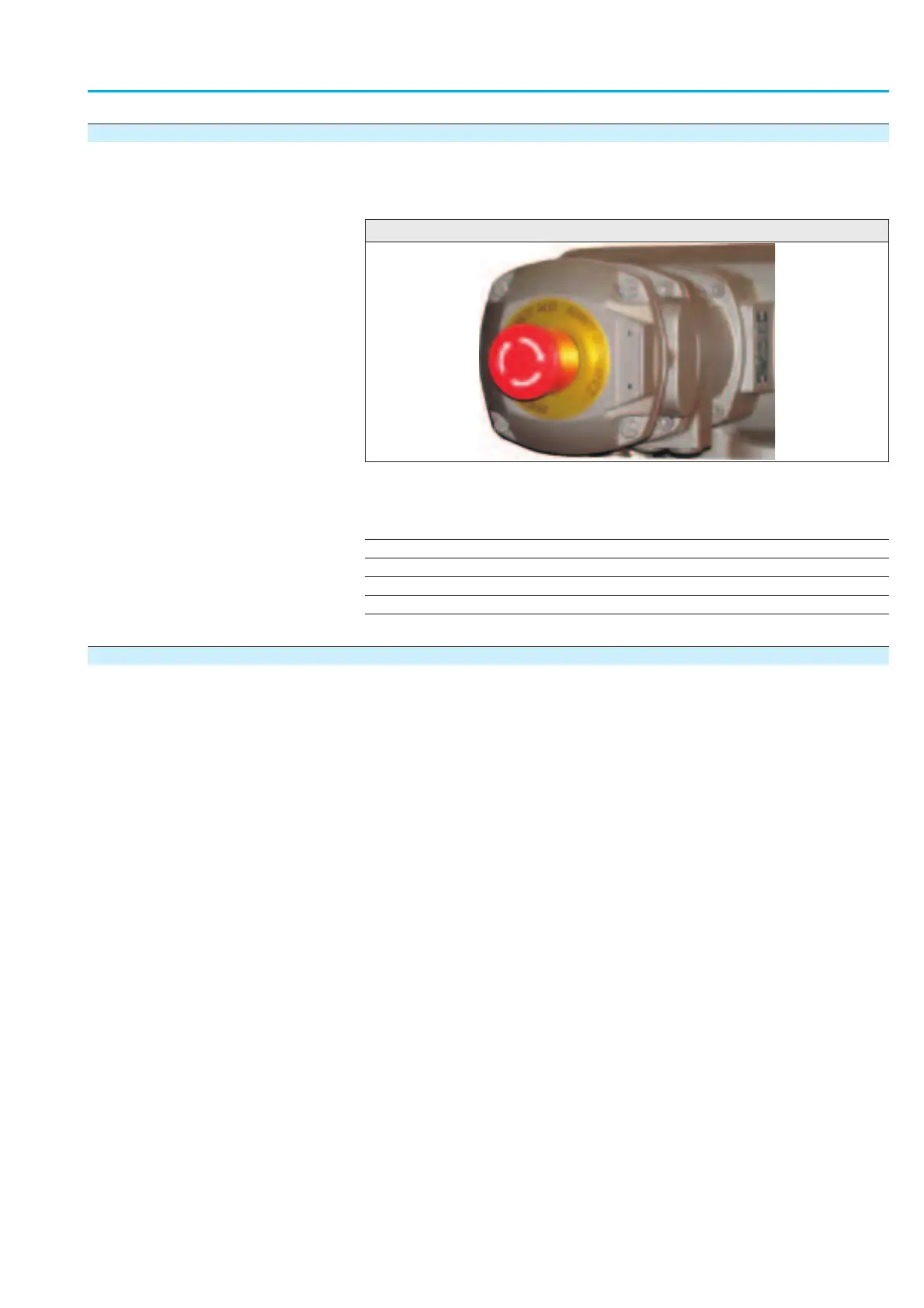
7.10 EMERGENCY STOP function (option)
As an option, the AUMATIC can be equipped with an EMERGENCY STOP
push button. When engaged, this EMERGENCY STOP interrupts the 24 V
AC control voltage of the contactors.
Information
The EMERGENCY STOP push button is not available for the ACExC, but
only for weatherproof versions of the AUMATIC.
Table of contents:
7.10.1 Description of the functions
7.10.2 Feedback signals on the display
6.13.3 Feedback signals via the fieldbus interface
7.10.3 Feedback signals setting via output contacts
7.10.4 Feedback signal setting via LEDs
7.10.1 Description of the functions
As soon as this EMERGENCY STOP button is operated, several steps are
performed in the AUMATIC:
.
The 24 V AC control voltage of the AUMATIC contactors is interrupted.
.
Switching off the operation command and cancelling a possibly set
self-retaining.
.
Option: The operation status of the EMERGENCY STOP button is indi-
cated by activating an output contact.
.
Option: The operation status of the EMERGENCY STOP button is indi-
cated by an indication light (LED) lighting up on the local controls.
.
EMERGENCY STOP status display indication with the EMCY STOP
ACTIVE
entry in the diagnostic indication S3 NOT READY IND
.
Display indication on EMERGENCY STOP status in status indication
S0: EMERGENCY STOP
.
Indication of the EMERGENCY STOP status by setting a bit in the pro-
cess representation (byte 13 – Not ready ind., bit 4 – Emcy STOP
active).
.
Option: Operation status indication of the EMERGENCY STOP button
via a bit within the definable range of the process representation
After unlocking the EMERGENCY STOP button, a possibly active operation
command will not immediatel
y be re-activated, but only upon confirmation
by the user which, in turn, resets the EMERGENCY STOP status.
After this, operation commands as well as emergency and failure operations
will immediately be performed.
Acknowledgement can be made:
.
via the Reset button in selector switch position LOCAL
.
or via the Profibus, Reset Bit of process representation (for this, the
selector switch must be in Remote control position).
75
Actuator controls
Manual AUMATIC AC 01.1/ACExC 01.1 Profibus DP
Figure 14