7.15 Combination fieldbus/standard interface (option)
The actuator controls is equipped with both a fieldbus interface and a paral
-
lel interface, if the
I/O STACK 2 parameter status shows I/O.
Æ
Via the menu to parameter:
MAIN MENU (M0)
CONFIGURATION (M4)
SETUP (M41)
I/O STACK 2 (M410Q)
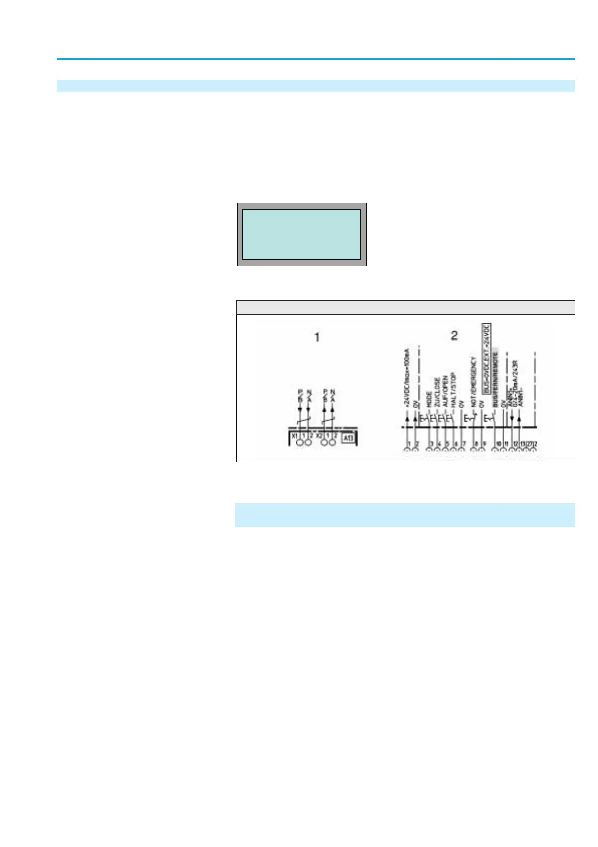
Figure 20 shows an extract of the wiring diagram with fieldbus interface (1)
and parallel interface (2):
Switching between operation commands via fieldbus and parallel
inputs
Ò Apply 0 V DC (input open) at B
US/REMOTE input:
Controls react to fieldbus signals only.
Ò Apply + 24 V DC (optional 115 V AC) at BUS/REMOTE input.
Controls reacts to parallel interface signals only:
MODE, CLOSE, OPEN, STOP, EMERGENCY, ANIN1+, ANIN1–
Information If a v
oltage of 0 V is present at the EMERGENCY input, the actuator per-
forms the set EMERGENCY operation (refer to page 38), irrespective of the
BUS/REMOTE input.
Information In the event of loss of bus communication, the external inputs do not auto-
matically take over!
Information Please refer to the AUMATIC AC 01.1/ACExC 01.1 Profibus DP manual
(fieldbus device integration) for details on feedback signals.
83
Actuator controls
Manual AUMATIC AC 01.1/ACExC 01.1 Profibus DP
VIEW
I/O STACK 2
I/O
C:ESC
Figure 20
1 Fieldbus interface 2 Parallel interface