7.10.2 Feedback signals on the display
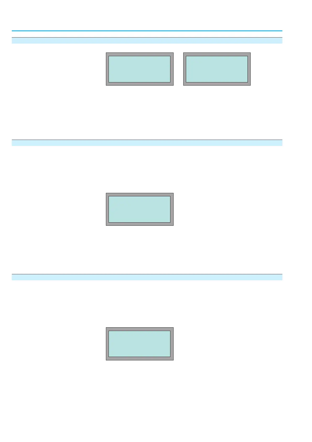
The following indications are displayed in status indications
S0 and S3 :
È
Description of the indications:
EMERGENCY STOP/EMCY STOP ACTIVE
The EMERGENCY STOP button has been operated and has put the
AUMATIC into the EMERGENCY STOP status. This status can only be
cancelled by unlocking the EMERGENCY STOP button and issuing a sub-
sequent RESET command.
7.10.3 Feedback signals setting via output contacts
Æ
Via the menu to parameter:
MAIN MENU (M0)
SETTINGS (M1)
I/O 1 (M14)
OUTPUT CONTACT1-5
È
Description of the parameter settings:
EMCY STOP BUTTON
The selected output contact is activated, after the EMERGENCY STOP but-
ton was operated.
This signal can be cancelled by unlocking the EMERGENCY STOP button.
7.10.4 Feedback signal setting via LEDs
Æ
Via the menu to parameter:
MAIN MENU (M0)
SETTINGS (M1)
LOCAL CONTROLS (M13)
LED1-4
È
Description of the parameter settings:
EMCY STOP BUTTON
The selected LED is illuminated after the EMERGENCY STOP button was
operated.
This signal can be cancelled by unlocking the EMERGENCY STOP button.
76
Actuator controls
AUMATIC AC 01.1/ACExC 01.1 Profibus DP Manual
NOT READY IND, S3
EMCY STOP ACTIVE
EMERGENCY STOP S0
EDIT M1412
OUTPUT CONTACT 1
EMCY STOP BUTTON
:EDIT ¿:OK C:ESC
EDIT M1313
LED 2
EMCY STOP BUTTON
:EDIT ¿:OK C:ESC