80-0000010B OM
133
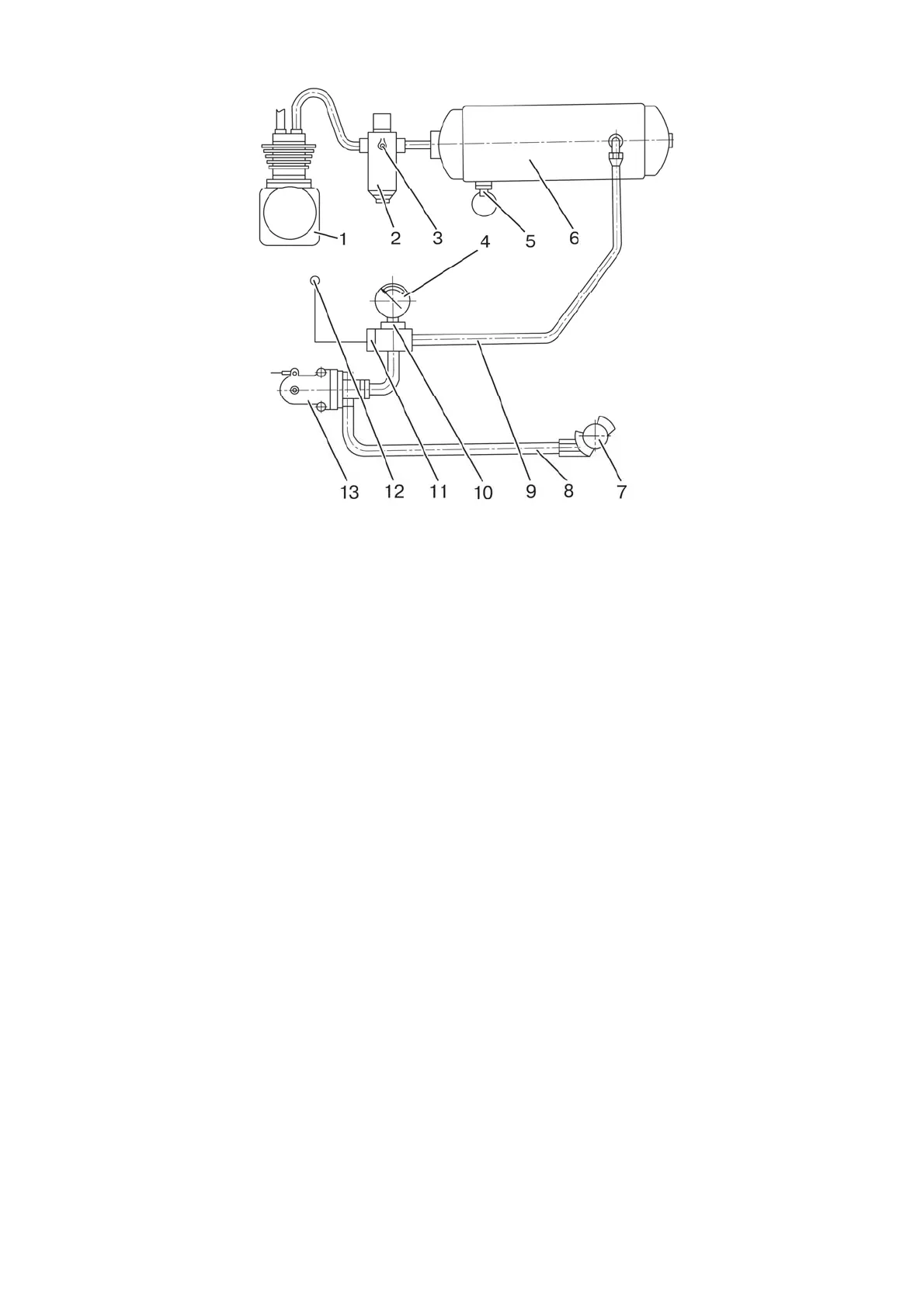
1 – pneumatic compressor; 2 – pressure regulator; 3 – air bleed valve; 4 – air
pressure indicator; 5 – condensate drainage valve; 6 – cylinder; 7 – coupling head;
8 – connection pipeline; 9 – pipeline; 10 – pressure sensor; 11 – emergency pressure
sensor; 12 – emergency pressure warning lamp; 13 – brake valve.
Figure 3.8.1 – One-line pneumatic drive.
Proceeding from the set forth, agricultural machine brake control is carried out in
two modes: direct and automatic.
Direct control of the agricultural machine brakes is carried out as a result of pres-
sure drop in connection pipeline 8 to zero MPa when the tractor is braking. In this case
compressed air supply into the pneumatic system of the agricultural machine stops.
Automatic brake control (automatic braking) is carried out in case of disconnection
of the coupling and detachment of the agricultural machine due to pressure drop in the
trailer connection pipeline.
To drain condensate from cylinder 6 condensate drainage valve 5 is provided. Con-
densate drainage is carried out by deflection of the plunger with ring to the side and up. Air
bleeding from the pneumatic drive (for tyre inflation and so on) is carried out through air
bleed valve 3 of pressure regulator 2.
3.8.2.2 Check and adjustment of the pneumatic system brake valve drive.
ATTENTION: CARRY OUT ADJUSTMENT OF THE PNEUMATIC SYSTEM BRAKE
VALVE DRIVE WITH THE SERVICE BRAKES PEDALS NOT PRESSED AND WITH THE
PARKING BRAKE FULLY DISENGAGED, WHICH SHALL BE PRELIMINARY ADJUST-
ED!
ATTENTION: CHECK AND IF NECESSSARY ADJUSTMENT OF THE PNEUMAT-
IC SYSTEM BRAKE VALVE DRIVE SHOULD BE CARRIED OUT AFTER ADJUSTMENT
OF THE OPERATION OF THE SERVICE BRAKE CONTROL AND ADJUSTMENT OF
THE PARKING BRAKE CONTROL!