80-0000010B OM
47
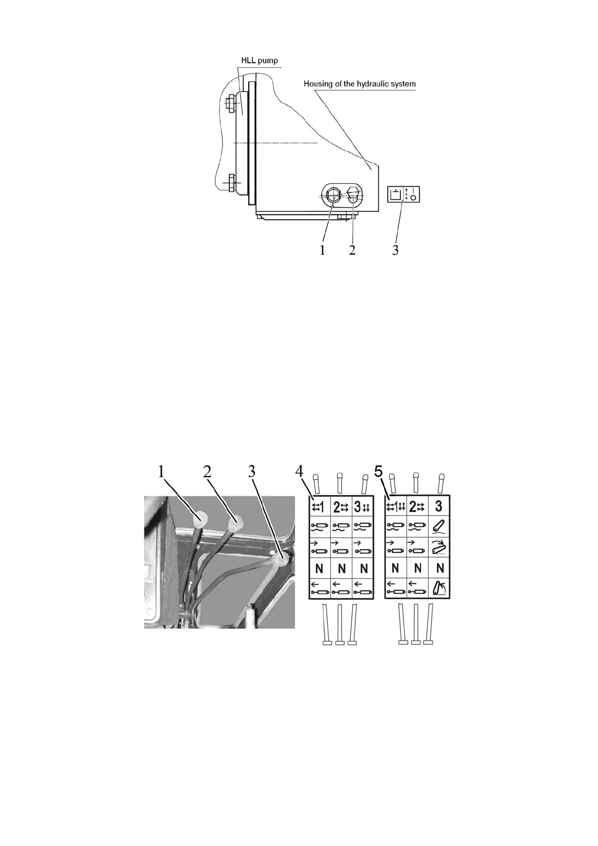
1 – roller to switch on HLL pump; 2 – bolt; 3 – diagram of HLL pump switching on.
Figure 2.16.1 – HLL pump control
Note – Position “HLL pump switched off” is shown in figure 2.16.1.
ATTENTION: SWITCH ON AND OFF THE HLL PUMP ONLY AT MINIMUM IDLE
SPEED OF THE ENGINE!
If the HLL defects occur, which result in oil leakage from hydraulic system, switch off
the HLL pump when you transport tractor to the repair site.
2.16.3 Remote hydraulic cylinders control
2.16.3.1 Control of the remote hydraulic cylinders with the installed distributor Р80-3/4-
111(222), РП70-1221.1С and the remote hydraulic cylinders and the RLL with the installed
distributor Р80-3/1-222, РП70-890.1
1, 2 – handles to control HLL distributor outlets (remote cylinders); 3 – handle to control
HLL distributor (Р80-3/4-111(222), РП70-1221.1С) outlets or RLL (Р80-3/1-222, РП70-890.1)
control; 4 – instruction plate with the distributor Р80-3/4-111(222), РП70-1221.1С control dia-
gram; 5 – instruction plate with the distributor Р80-3/1-222, РП70-890.1 control diagram.
Figure 2.16.2 – The remote hydraulic cylinders control with the installed distributor Р80-
3/4-111(222), РП70-1221.1С and the remote hydraulic cylinders and the RLL with the installed
distributor Р80-3/1-222, РП70-890.1
Each of three handles 1, 2, 3 (figure 2.16.2) of the distributors Р80-3/1-222, Р80-3/4-
111(222), РП70-1221.1С, РП70-890.1 has four positions:
- “Floating” – upper most fixed position;