80-0000010B OM
206
CHANGING ENTERED VALUES OF ANY OTHER PARAMETERS (FACTORY SET-
TINGS) IS PROHIBITED.
When activating the instrument scales’ illumination, i.e. when shifting the central light switch 10
(figure 2.24.1) into position II “Dashboard illumination and marker lights are ON” and position III “Po-
sition II consumers and front headlights are ON”, the glowing brightness of the multifunctional indica-
tor display of the PTO indicator segments is decreased automatically.
3.18.5 Installation and adjustment of speed sensors
To install a speed sensor (either left or right) proceed as follows:
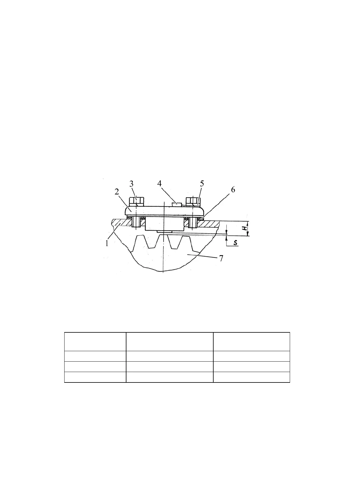
- set driven gear 7 (figure 3.18.3) so that its tooth faces the hole in the cover of rear
axle 1;
- to ensure gap S, measure dimension H and install the necessary amount of ad-
justing shims 6 as per table 3.18.3;
- install the “ground” wire 4 of sensor 2 under any of bolts 3 with a spring washer 5;
- install bolts 3 on sealant and tighten with torque from 10 to 15 Nꞏm.
1 – rear axle cover; 2 – speed sensor; 3 – bolt; 4 – “ground” wire; 5 – spring washer;
6 – shim; 7 – driven gear.
Figure 3.18.3 – Speed sensor installation
Table 3.18.3 – Speed sensor installation
Н, mm
Number of shims 6
(figure 3.18.3)
S, mm
11.25 - 12.00 5 2.05-2.80
12.10 - 13.00 4 1.90-2.80
13.10 – 13.80 3 1.90-2.60