80-0000010B OM
161
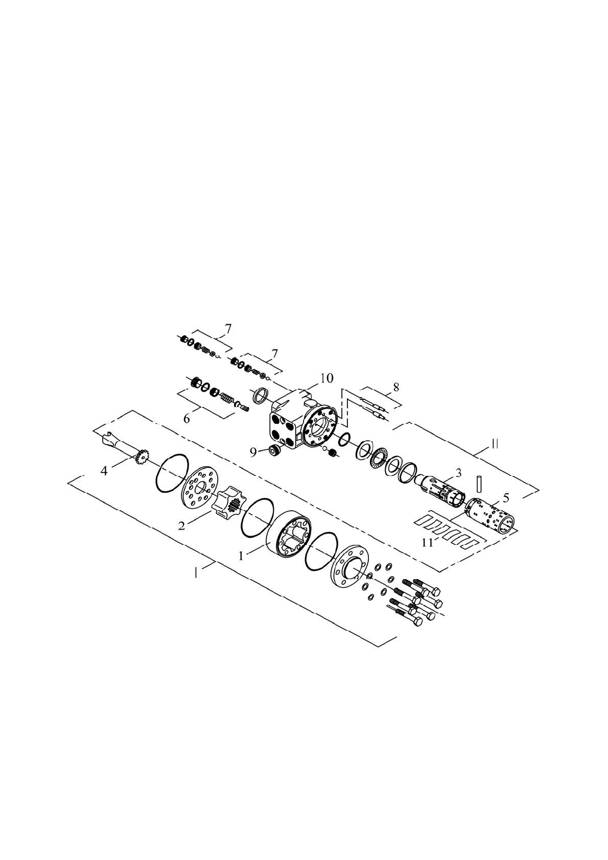
3.12.2 Dosing pump
Dosing pump is of gerotor type with an “open center” and no reaction on the steer-
ing wheel includes housing 10 (figure 3.12.4), pumping unit I, distributor II, two anti-shock
valves 7, safety valve 6, two air-inlet valves 8 and back-flow valve 9.
Gerotor pumping unit I consists of stator 1 secured on housing 10 and rotating rotor
2, connected to spool 3 through cardan shaft 4.
Distributor II consists of sleeve 5, set of plate springs 11 and spool 3, connected by
splines with shank of steering column drive shaft.
The back-flow valve provides operation of the dosing pump in the manual control
mode as a manual pump, when the feed pump is faulty.
Safety valve 6 prevents pump and HSC hydraulic system from overloading, limiting
maximum pressure in the pressure line in the range from 14 to 15 MPa.
Anti-shock valves 7 (right and left) protect hoses of cylinder hydraulic lines from
peak pressures, arising in the cavities of the hydraulic cylinder at the moment of steering
wheels running-over obstacles. Anti-shock valves adjusting pressure is from 20 to 21 MPa.
Air-inlet valves 8 (right and left) prevent HSC hydraulic system from vacuum and
cavitation when anti-shock valves actuate.
1 – stator; 2 – rotor; 3 – spool; 4 – cardan shaft; 5 – sleeve; 6 – safety valve;
7 – anti-shock valves; 8 – air-inlet valves; 9 – back-flow valve; 10 – housing; 11 – plate
springs; I – pumping unit; II – distributor.
Figure 3.12.4 – Dosing pump