80-0000010B OM
163
3.13 Hydraulic power steering
3.13.1 General information
Hydraulic booster is designed to control steering of the guiding wheels and to re-
duce force on the steering wheel when tractor is turning. The hydraulic booster is mounted
on the front beam of the tractor, and is a steering mechanism with a worm gear pair inter-
acting with hydraulic units – a power cylinder and a distributor valve. Hydraulic booster dis-
tributor valve 13 (figure 3.13.2) connects by oil pipelines to the pump mounted on the en-
gine, to the power cylinder and hydraulic booster housing 5 (figure 3.13.1), which is at the
same time oil tank of the steering control hydraulic system. In the drain line there are pres-
sure-relief valve 10 and filter 15 (figure 3.13.2).
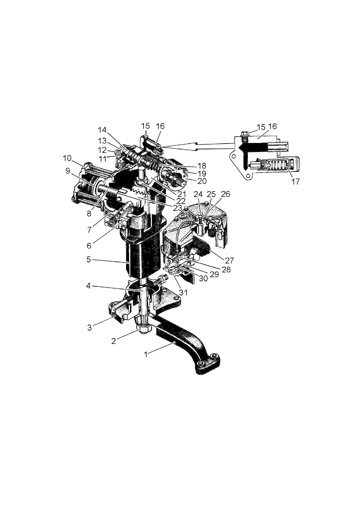
1 – drop arm; 2 – drop arm nut; 3 – drain plug; 4 – turning shaft; 5 – housing;
6 – rack stop; 7 – adjusting shims; 8 – rod; 9 – piston; 10 – front cylinder cover; 11 – thrust
bearing; 12 – washer; 13 – spherical nut; 14 – spool; 15 – plug; 16 – valve cover; 17 – ad-
justing valve screw; 18 – worm; 19 – adjusting bushing fastening bolt; 20 – adjusting bush-
ing; 21 – sector; 22 – nut; 23 – rack; 24 – adjusting bolt; 25 – upper cover; 26 – locknut;
27 – drain filter; 28 – pressure-relief valve; 29 – control cock; 30 – spool of differential
lock sensor; 31 – control cock handwheel.
Figure 3.13.1 – Hydraulic power steering