80-0000010B OM
232
4.2.11 Front wheel track formation
4.2.11.1 General information
Tractor BELARUS-80.1 is equipped with a non-driving front axle (80-3000030).
Tractor BELARUS-82.1 is equipped with an FDA with bevel wheel gear groups (72-
2300020-А-04 or 72-2300020-А).
Tractor BELARUS-820» is equipped with an FDA with planetary-spur wheel gear
groups (822-2300020-02 with long beam, 822-2300020-04 with short beam).
The rules of forming the front wheels track for BELARUS-80.1 tractor with non-
driving front axle are given in section 4.2.11.2.
The rules of forming the front wheels track for BELARUS-80.1 tractor with FDA with
bevel wheel gear groups are given in section 4.2.11.3.
Information on possible options of setting the front wheel track of BELARUS-820
tractor with FDA with planetary-spur wheel gear groups is given in section 4.2.11.4.
4.2.11.2 Front wheel track formation of tractors equipped with non-driving front axle
4.2.11.2.1 Front wheel track formation of tractors, equipped with non-driving front
axle and HSC.
The tractor track is changed both by extending the axle and by re-placing the
wheels from one sideboard to the other.
The configuration of two-wheel axle allows to change the front wheel track from
1450 to 1750 mm with the interval of 100 mm, and from 1550 to 1850 mm with the interval
of 100 mm, depending on the wheel mounting diagram.
To set a required track do the following:
- brake the tractor using the parking brake. Put wheel chocks at the front and back
of rear wheels; the engine shall be stopped;
- set a jack under one of the sides of the front axle, jack up the wheel until it lifts off
the ground;
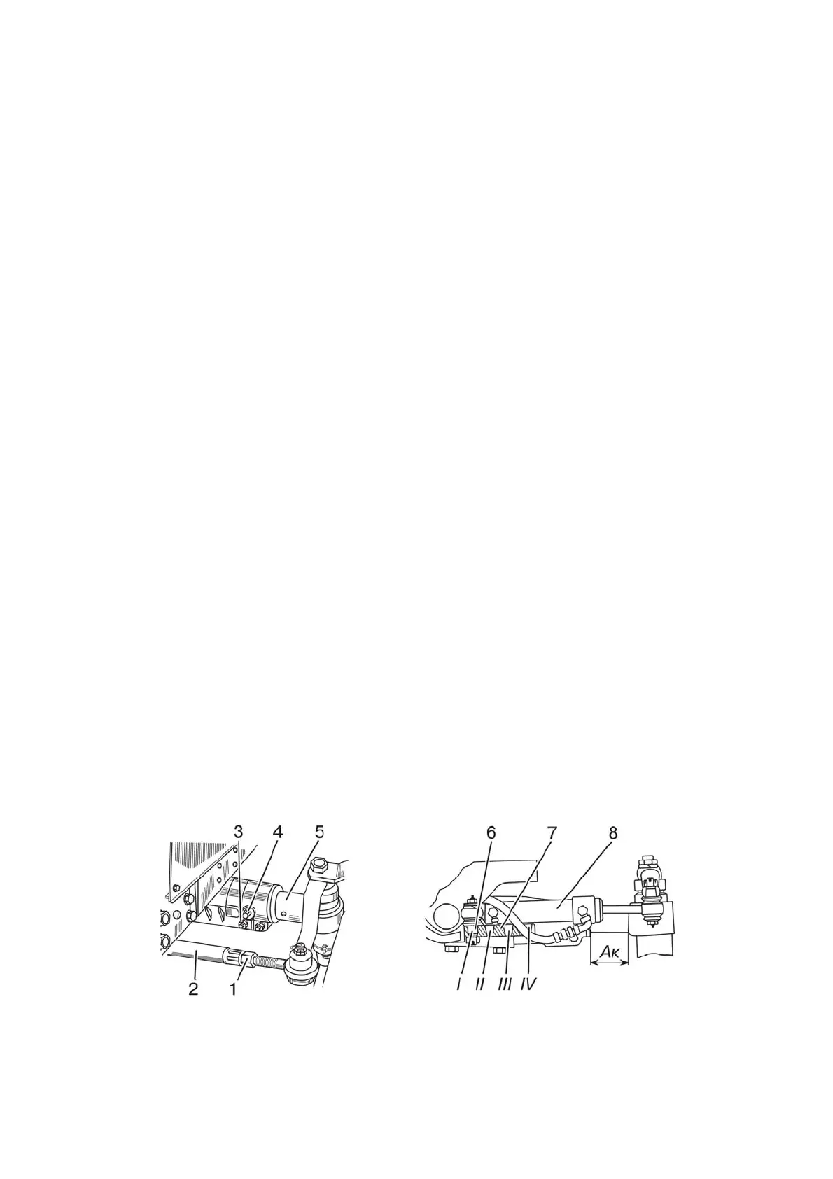
- release nuts of tie bolts 3 (figure 4.2.8), remove pin 4 that locks the extensible
knuckle 5, loosen the tightening of two locknuts 1 at the ends of steering link tube 2;
- detach cylinder 8 from bracket 7;
- move extensible knuckle 5 inside or outside the front axle body, in accordance
with table 4.2.7 and figure 4.2.9;
- install pin 4 (figure 4.2.8) and tighten bolts 3;
- repeat the listed operations for the other end of the front axle;
- install pin 6 of cylinder 8 in hole of bracket 7 according to table 4.2.6;
- adjust toe-in of front wheels, tighten nuts 1 of steering link tube 2.
a) rear view b) front view
1 – locknut; 2 – steering link tube; 3 – bolt; 4 – pin; 5 – extensible knuckle; 6 – pin of
cylinder; 7 – bracket; 8 - cylinder.
Figure 4.2.8 – Front wheel track formation on tractors with front non-driving axle and HSC