80-0000010B OM
31
2.5 Instrument board
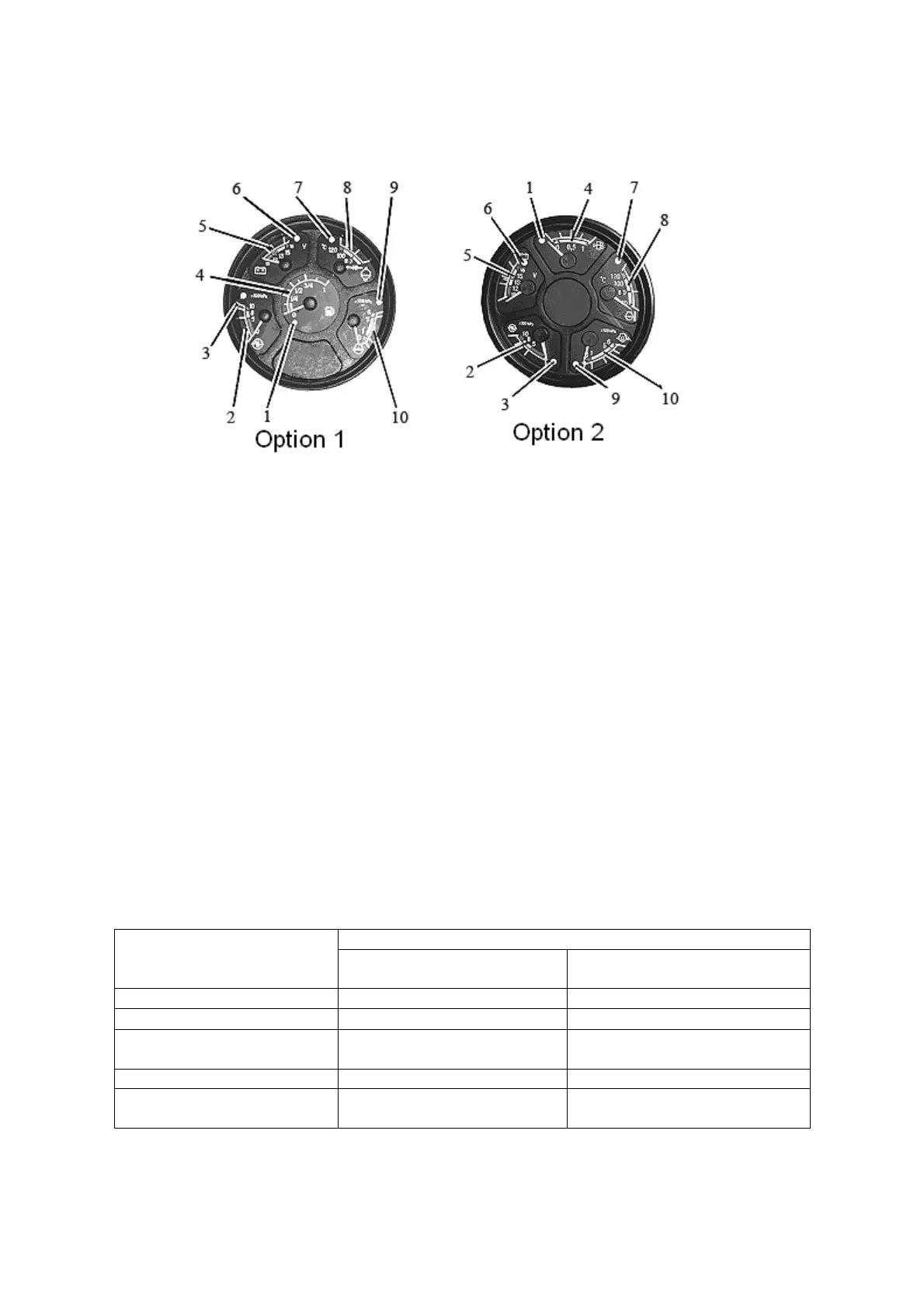
The Instrument board 4 (figure 2.1.1) includes five indicators with five pilot lamps,
as shown in figure 2.5.1.
1 – backup fuel level in tank warning lamp; 2 – air pressure in the pneumatic system
indicator; 3 – emergency air pressure in the pneumatic system warning lamp; 4 – fuel level in
tank indicator; 5 – voltage indicator; 6 – idle warning lamp; 7 –engine coolant emergency tem-
perature warning lamp; 8 – engine coolant temperature indicator; 9 – emergency oil pressure
in the engine lubrication system warning lamp; 10 – oil pressure in the engine lubrication sys-
tem indicator.
Figure 2.5.1 – Instrument board
2.5.1 Scale of the air pressure in the pneumatic system indicator 2 (figure 2.5.1) has
three sectors:
- working – from 500 to 800 kPa (green color);
- emergency (two) — from 0 to 500 kPa and from 800 to 1000 kPa (red color).
In the indicator scale warning lamp (red color) 3 is built in, which lights up when
pressure in the pneumatic system decreases below 500 kPa.
2.5.2 Voltage indicator 5 (figure 2.5.1) indicates accumulator batteries voltage when
the engine is dead, when the starter and instruments switch key (figure 2.2.2) is in the posi-
tion “I”. When the engine is running voltage indicator shows voltage in the on-board tractor
network, which generator sets.
The state of the power supply system, depending on the position of the needle on
the indicator scale, is given in table 2.5.1.
Table 2.5.1 – State of the power supply system
Secto
in the voltage indi-
cator scale 5 (figure 2.5.1),
color
State of the power suppl
s
stem
With engine running With dead engine
13,0
15,0 В,
reen Normal char
in
mode -
10,0
12,0 В, red Generato
does not work
B discharged
12,0 – 13,0 В, yellow
No charge in AB
low char
e volta
e
AB has normal charge
15,0
16,0 В, red
B rechar
e
-
White mark in the yellow
secto
-
Rated no-load voltage of cell
12,7 V
ATTENTION: IF VOLTAGE INDICATOR SHOWS NO CHARGING OF AB, CHECK THE
CONDITION AND TENSION OF GENERATOR DRIVE BELT!