80-0000010B OM
96
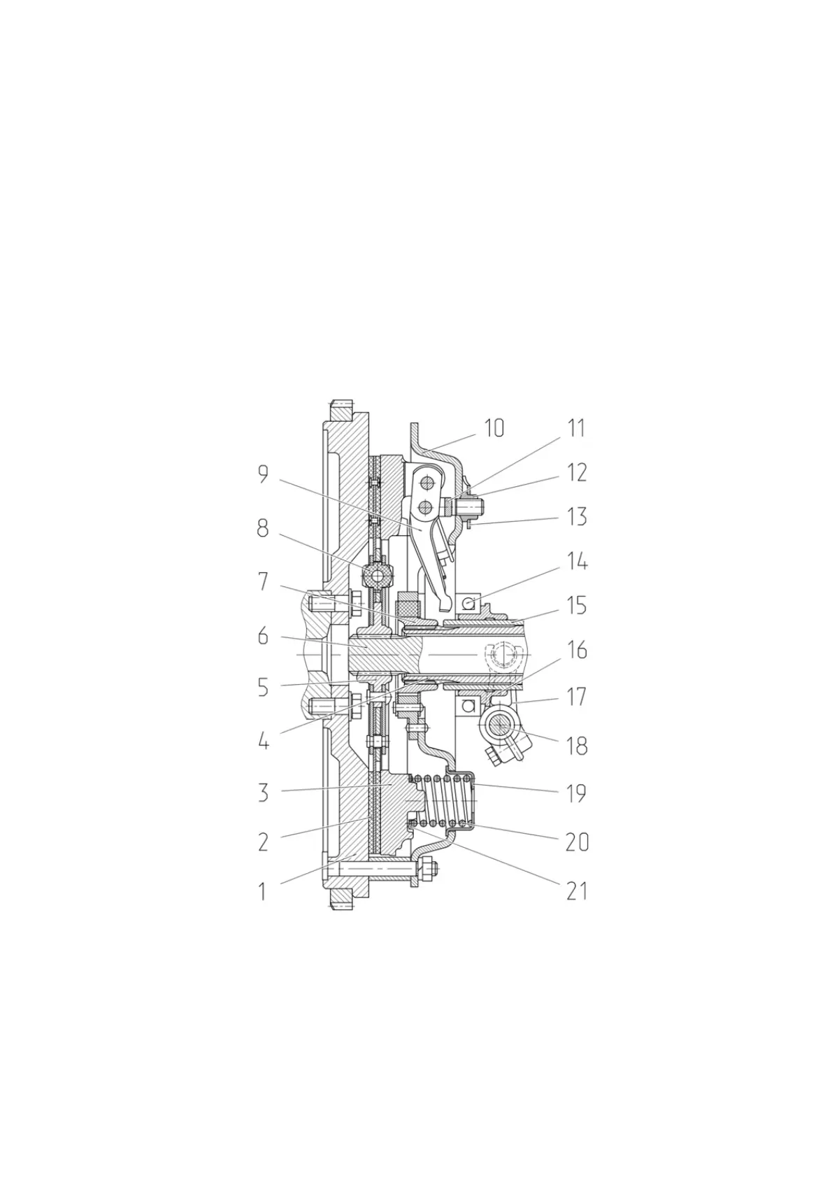
3.2 Clutch
3.2.1 Clutch coupling
On flywheel 1 (figure 3.2.1) of the engine a dry, single-disc, spring-loaded coupling
clutch is installed.
Flywheel 1 and pressure plate 3 are the drive portion of the coupling clutch.
The driven portion of the clutch includes driven disc 2 (with asbestos free liners) with
torque vibration damper 8, mounted on output shaft 6.
On tractors “BELARUS-80.1/82.1/820” the necessary force of pressing the rubbing
surfaces of the drive and driven portions is provided by nine springs 20.
Between floating bushing 7, connected to PTO drive shaft 4, and bearing plate 10,
elastic elements are mounted. The clutch is engaged and disengaged by means of shifter
16 with release bearing 14, which shifts along bracket 15. Yoke 17 of the shifter with shaft
18 are connected by the arm with the clutch pedal. Greasing of release bearing 14 is car-
ried out through the grease fitting, screwed into the shifter yoke trunnion.
1 – flywheel; 2 – driven disc; 3 – pressure plate; 4 – PTO drive shaft;
5 – hub; 6 – output shaft; 7 – floating bushing; 8 – torque vibration damper; 9 – release
lever; 10 – bearing plate; 11 – fork; 12 – nut;
13 – locking plate; 14 – release bearing; 15 – shifter bracket;
16 – shifter ; 17 – withdrawal fork; 18 – control shaft; 19 – cup;
20 – pressure spring; 21 – insulating washer.
Figure 3.2.1 – Clutch coupling of tractors “BELARUS-80.1/82.1/820”