80-0000010B OM
191
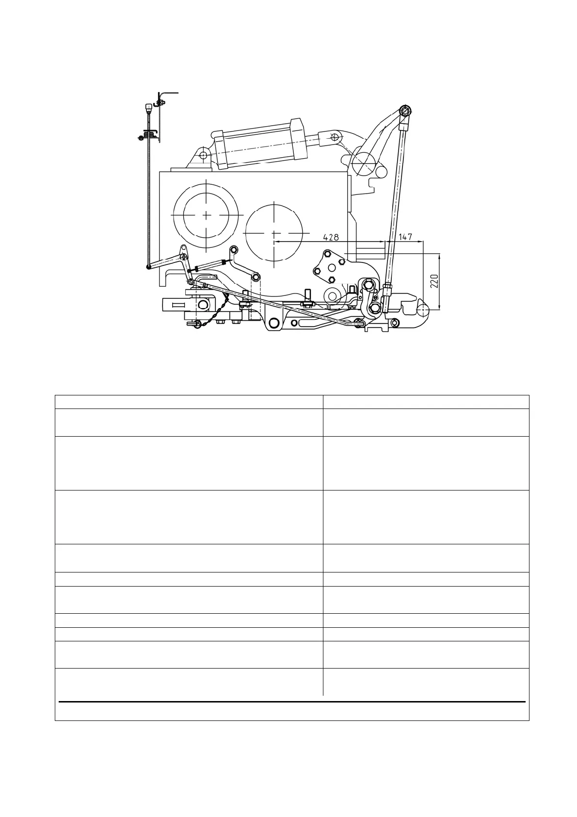
3.17.2 Tow hitch TSU-2 (hydraulic hook) and combined device TSU-2M-02 (with
hydraulic hook set in working position and pendulum set in additional position)
Figure 3.17.1 – The diagram of TSU-2 (hydraulic hook) and TSU-2М-02 (combined
device with hydraulic hook set in working position)
Table 3.17.1 – Basic parameters and coupling dimensions TSU-2 (hydraulic hook)
Dimension type (version) TSU-2 (hydraulic hook)
1 Mounting location Fastening in lower and side parts of the
rear axle case
2 Purpose For connection and coupling of agri-
cultural trailed and semi-trailed ma-
chines with travel wheels, semi-
trailers
3 Peculiarities of construction Hydraulic hook with control through
lift linkage, provides automatic hitch
with tow eyes of agricultural ma-
chines and semi-trailers
4 Distance between PTO shaft end and connect-
ing pin axis, mm
147
5 Vertical load in hitch point, not more, kN 12
6 Trailing appliance steering angle, in horizontal
plane, degrees, not less than
±60
7 Size of hook horn sphere, mm 47
8 Protective device type Safety chain (rope)
1)
9 Connection point of protective device to the
tractor
Bracket bores on tow hitch
10 Relative calculated value of axial forces (D),
kN, not more than
56,1
1)
Imрlement accessories