80-0000010B OM
177
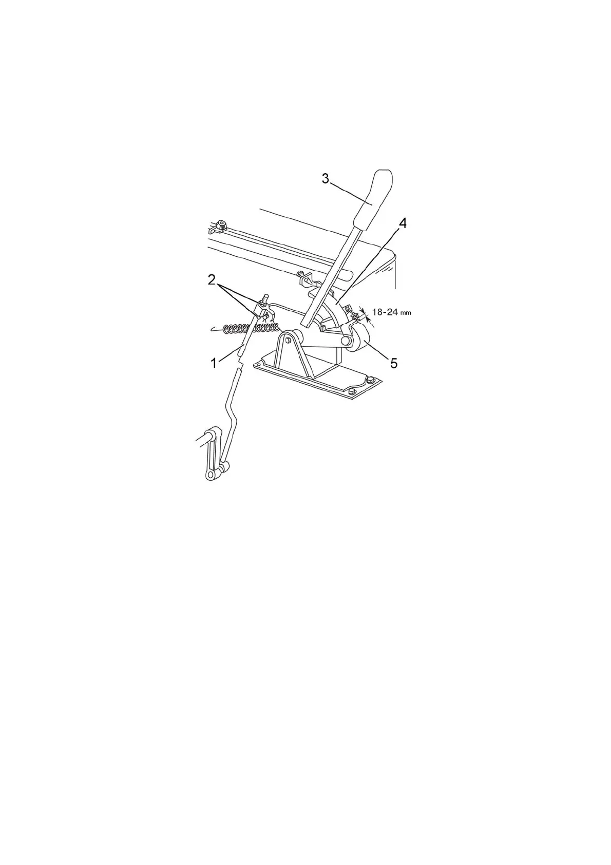
3.15.2 Adjustment of draft (position) control
3.15.2.1 Adjustment of draft control operating link
Adjust operating link of the control in the following way:
By means of nuts 2 (figure 3.15.9) adjust the length of link 1 of the draft control in such a
way, that when lever 3 is moved in the rear most position along tractor travel clearance in
the range 18…24 mm forms between rubber roller 5 and the edge of sector 4.
1 – link; 2 – nut; 3 – lever; 4 – sector; 5 – rubber roller
Figure 3.15.9 – Adjustment of the draft control operating link
3.15.2.2 Adjustment of draft sensor
Adjust draft sensor in the following way:
- set switch 1 (figure 3.15.10) to middle position;
- take off central link 11 of the lift linkage, mount pin 12 of the central link on the
upper hole of eyebar 10;
- by means of additional lever 9 turn the eyebar around pin 14 in the direction of ar-
row “A” until spring 16 compresses fully. After the load from the lever is released the eye-
bar has to return to the initial position, in this case the sensor stroke, measured on the
shifting of draft link 6 shall make not less than 11 mm;
- after making sure that the sensor is in good condition, unlock castellated nut 13,
tighten it until compression of the sensor springs starts, then tighten it again until the slots
in the nut align with the cotter pin hole and forelock.
3.15.2.3 Adjustment of position link
Adjust position link in the following way:
- set switch 1 (figure 3.15.10) to middle position;
- raise lift linkage in upper most position;
- adjust the length of link 5, so that switch 1 goes freelly with its lug into the slot of
position lever 2, after this shorten link 5 by 1 turn of adjusting nuts 8.