80-0000010B OM
188
To install rear ends of lower links 5 (figure 3.16.11), dismount crossbar 4, and with the help
of eyes 4, pins 2 and split pins attach the rear ends of lower links by the front ends of lower links 1,
and attach limiting buckles 6 to eyeloops 3.
ATTENTION: WHEN MOUNTING THE FRONT ENDS OF LOWER LINKS ON THE LOW-
ER LINKS AXES (DELIVERY CONDITION FROM THE FACTORY), TO AVOID BREAKAGE, THE
TELESCOPIC BUCKLES SHALL BE MOUNTED ONLY ON THE SECOND FROM BELOW
HOLES OF THE BRACKETS (POSITION 2 IN FIGURE 3.16.3)! IT IS FORBIDDEN TO USE PO-
SITIONS ON THE BRACKET 1, 3 AND 4 SHOWN IN FIGURE 3.16.3!
ATTENTION: ON TRACTORS “BELARUS-80.1/82.1/820” MOVEMENT WITH TRAILED
MACHINES, ATTACHED TO TСУ-1Zh, AT A SPEED ABOVE 15 KM/H IS FORBIDDEN!
ATTACHMENT OF TRAILERS AND SEMI-TRAILERS TO THE HITCH DEVICE TСУ-1Zh
IS FORBIDDEN.
When operating the tractor with the use of tow hitch (TСУ-1Zh) the buckles shall be fully
locked in working position. For that, it is necessary to mount the lower links together with crossbar
4 in horizontal position and to lock the buckles fully in working position, as set forth in subsection
3.16.2.1 “Buckles”.
Note – Basic parameters and characteristics of the TСУ-1Zh are represented in subsection
3.17 “Tow hitches”.
3.16.2.4.3 Telescopic lower links and double crossbar
Upon request tractors “BELARUS-80.1/82.1/820” can be completed with reinforced
RLL with the telescopic lower links, which are mounted on axes Ø 35 mm instead of axis
Ø 32 mm (on tractors “BELARUS-80.1/82.1/820” additional axes also Ø 35 mm). If neces-
sary, the length of the telescopic buckles can be adjusted stepwise in the limits ± 80 mm
from the middle position (attained lengths of links – 805 mm, 885 mm, 965 mm), in this
case lifting capacity of the RLL will change (805 mm – maximum lifting capacity, 965 mm –
least lifting capacity).
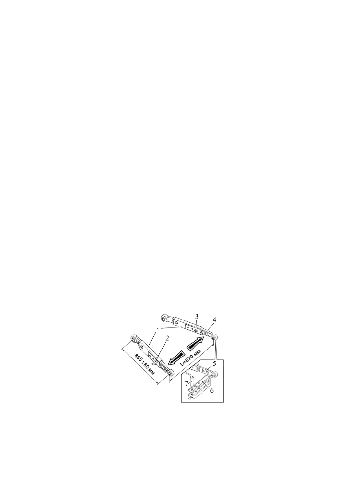
To set the required length of the lower link it is necessary to carry out the following:
- unscrew nut 3 (figure 3.16.12) and take out eyeloop 2;
- shift rear end 4 of the telescopic link into the required position, mount the eyeloop in the
corresponding hole and screw the nut;
- set the required length of the second link in the same way.
Eyeloops 2 shall be mounted only on the holes, which are shown in figure 3.16.12.
1 – front end of the telescopic link; 2 – eyeloop; 3 – nut; 4 – rear end of the telescopic link;
5 – end piece of the crossbar; 6 – crossbar; 7 – pivot.
Figure 3.16.12 – Setting of the double crossbar on the telescopic links
Note – in figure 3.16.12 the position of the telescopic links for a length of 885 mm is
shown