80-0000010B OM
66
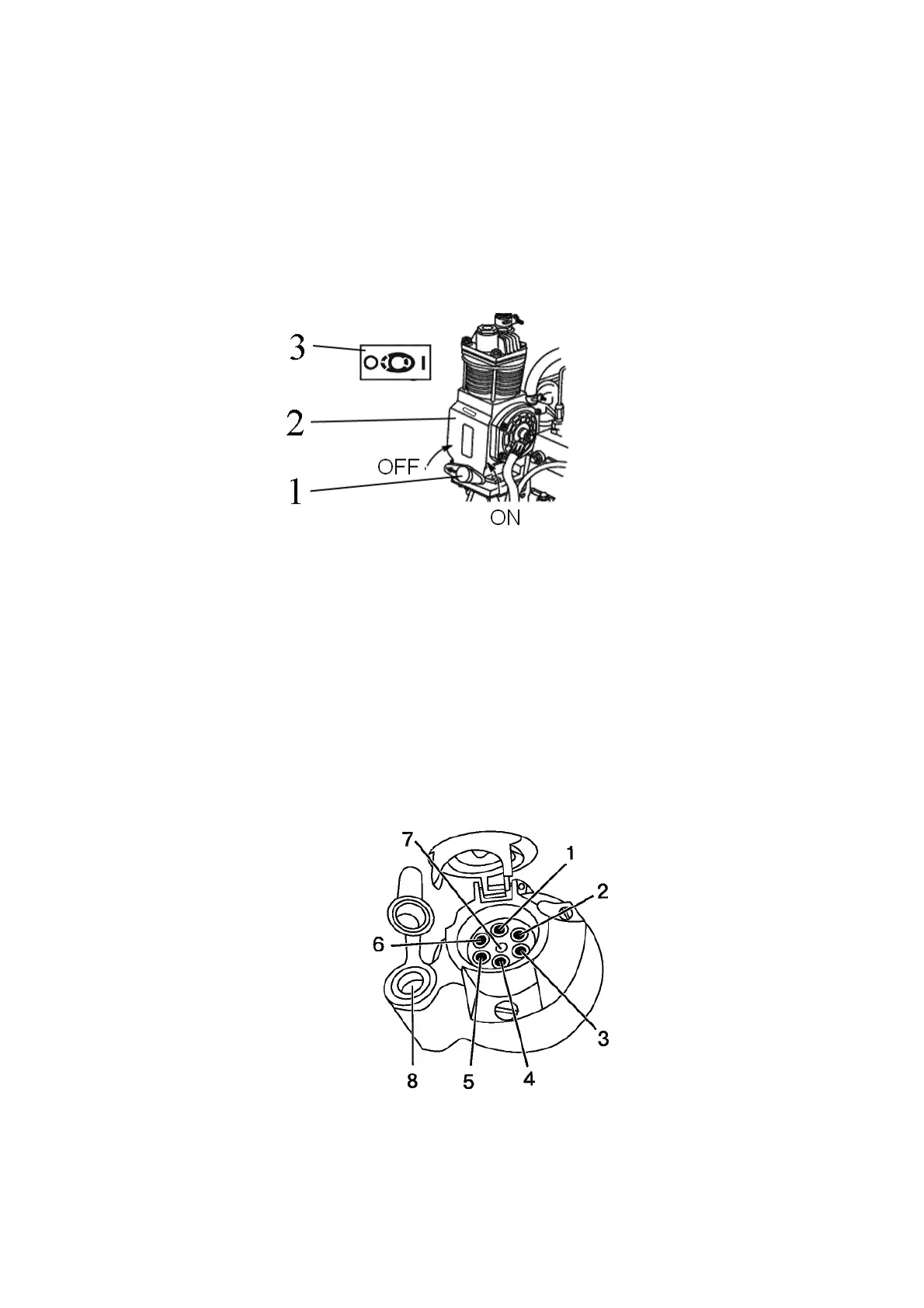
2.21 Pneumatic system compressor control
Handle to turn pneumatic system compressor 1 on (figure 2.21.1) has two positions:
left (the arrow on the handle is directed forward as viewed along tractor movement)
– “compressor off”,
right (the arrow on the handle is directed backward to tractor cab) – “compressor
on”.
ATTENTION: TURN THE PNEUMATIC SYSTEM COMPRESSOR ON AND OFF ONLY WITH THE ENGINE
NOT RUNNING OR WITH MIN. IDLE SPEED OF THE ENGINE!
1 – handle to turn the pneumatic system compressor on; 2 – pneumatic system
compressor; 3 – diagram of pneumatic system compressor control.
Figure 2.21.1 – Pneumatic system compressor control
Note – In figure 2.21.1 the position “the pneumatic system compressor is on” is
shown.
2.22 Connector elements of the electrical equipment
2.22.1 Socket to connect electrical equipment of coupled agricultural machines
A standard seven-pin socket with an additional receiver to connect a portable lamp (figure
2.22.1) is intended to connect current consumers of a trailer or trailed agricultural implement. It is
mounted on the rear cab support. A male plug of wire harness from trailer or coupled agricultural
implements is connected to the socket.
1 – left turn indicator; 2 – horn; 3 – ground; 4 – right turn indicator; 5 – right clear-
ance lamp; 6 – brake light; 7 – left clearance lamp; 8 – receiver to connect a portable lamp
or other electrical elements with useful current up to 8A.
Figure 2.22.1 – Assignment of seven-pin socket terminals with an additional receiv-
er to connect a portable lamp.