80-0000010B OM
125
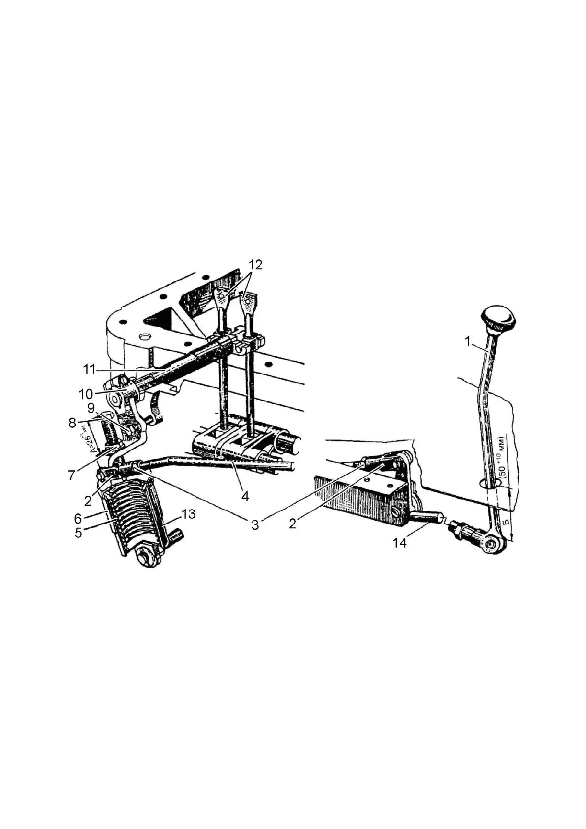
3.5.5 Rear PTO control on tractors with canopy frame or canopy base on the
basis of a small cabin
On tractors with canopy frame and canopy base on the basis of a small cabin me-
chanical control of rear PTO is installed. Rear PTO control diagram is shown in figure
3.5.3.
Lever 1 (figure 3.5.3) has two positions:
-“PTO engaged” – upper most position;
-“PTO disengaged” – rear most position.
Lever 1 should be set and fixed in two extreme positions only under action of spring
5. Pressing it in by hand is not allowed.
Size Б shall be 50
+10
mm (figure 3.5.3) with rear most position of lever 10. Size Б is
adjusted by changing length of link 4. To change length of link 4 it is necessary to unlock
nut 3 and turn the fork several turns in the required direction, to get size Б (50
+10
mm).
1 – control lever; 2 – adjusting fork; 3, 7 – nuts; 4 – link; 5 – spring; 6 – out-
er sleeve; 8 – stop bolt; 9 – set bolt (only for adjustment); 10 – control shaft lever; 11 –
control shaft; 12 – adjustment screws; 13 – inner sleeve; 14 - lever.
Figure 3.5.3 – PTO mechanical control on tractors with canopy frame or canopy
base on the basis of a small cabin