80-0000010B OM
199
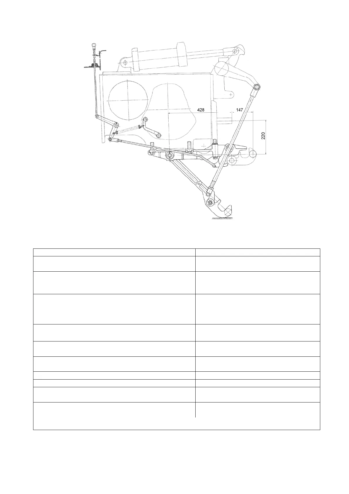
3.17.10 Tow hitch TSU-2 (autonomous hydraulic hook)
Figure 3.17.10 – Mounting diagram of TSU-2 (autonomous hydraulic hook)
Table 3.17.5 – Basic parameters and coupling dimensions of TSU-2 (autonomous
hydraulic hook)
Dimension t
pe
version
TSU-2
autonomous h
draulic hook
1 Mounting location Fastening in the lower part of the rear
axle case and PTO cove
2 Purpose To connect and couple agricultural
trailed and semi-trailed machines with
travel wheels, semi-trailers
3 Peculiarities of construction Hydraulic hook with control through
lift linkage, provides automatic hitch
with two eyes of the agricultural ma-
chines and semi-trailers
4 Distance between PTO end and connecting pin
axis, mm
147
5 Vertical load on tow hitch in hitch point, not
more, kN
10
6 Trailing appliance steering angle, in horizontal
plane, de
rees, not less than
±60
7 Size of hook horn sphere, mm 47
8 Protective device t
pe Safet
chain
rope
1)
9 Connection place of the protective device to the
tractor
Bracket bores on tow hitch
10 Relative calculated value of axial forces (D),
kN, not more
56,1
_________________________________________________________________________________________________________
1)
Implement accessor
.