80-0000010B OM
198
The pendulum, which is both a part of the combined device, and mounted separate-
ly, has the following mounting variants:
- two length positions;
- three positions in transverse plane.
To change the length position it is necessary:
- take out pin 6 (figure 3.17.8) from bracket 10;
- shift the pendulum in assembly until the second bore of the pendulum eyebar 1
aligns with the bore in bracket 10;
- lock new position of the pendulum with pin 6.
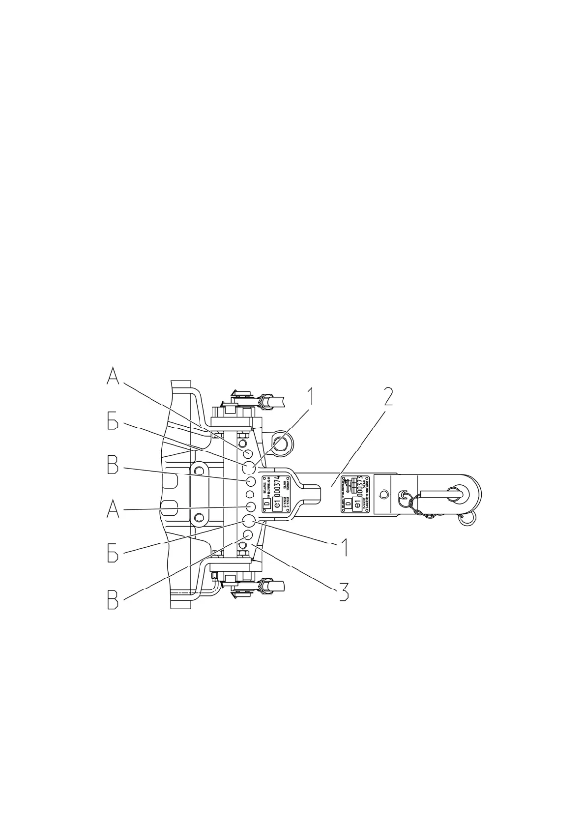
To shift implement axis relative to tractor axis pendulum 2 (figure 3.17.9), apart
from the main position, can be mounted at an angle (4±1)º relative to longitudinal axis of
tractor:
- position (4±1)º relative to tractor axis – pendulum 2 is locked with pins 1, mounted
in bores A of bracket 3;
- main position – the pendulum is locked with pins 1, mounted in bores Б of bracket
3;
- position - (4±1)º relative to tractor axis – the pendulum is locked with pins 1,
mounted in bores B of bracket 3.
1 – pin; 2 – pendulum; 3 – bracket of tow hitch.
Figure 3.17.9 – Variants of pendulum mounting relative to longitudinal tractor axis